Isuzu Rodeo UE. Manual — part 512
7B–80
MANUAL TRANSMISSION
21. Apply a 3 mm (1/8 in) bead of RTV sealant to the
sealing surface of the extension housing.
Lubricate the detent/guide plate in the extension
housing with lithium grease. Install the detent ball(3)
in the “3–4” position of the detent pattern of the plate.
Place the offset lever(3) with detent spring(3) in the
extension housing detent/guide plate area and push
the extension housing(2) against the case and shift
cover(5).
220RW059
Guide the offset lever(3) onto the shift shaft as you
push the extension housing(2). You will have to
compress the detent spring(3) against its ball(3) to fit
the parts easily.
230RS026
Apply sealer to the threads of the top two extension
housing-to-case bolts and install them. Install the
other six bolts as well. Tighten the bolts, using a 15
mm socket and a torque wrench.
Torque: 30 N·m (23 lb ft)
Apply sealer to the threads of the back-up lamp
switch and the drain plug and install them, using
suitable wrenches.
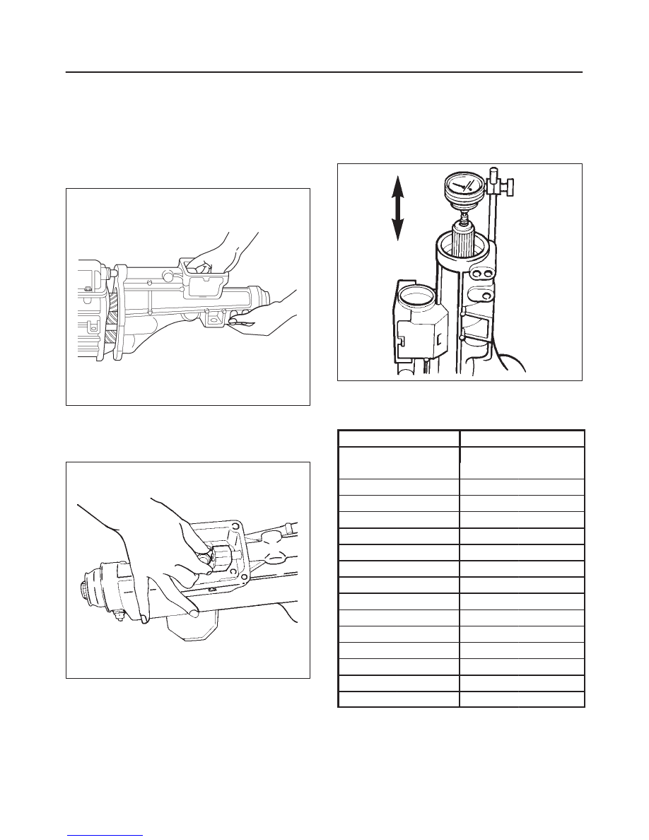
22. Install the offset lever-to-shift shaft roll pin(1), using a
hammer.
23. Turn the transmission case on end, and mount a dial
indicator on the extension housing. Set up the
indicator to measure input/mainshaft end play. Move
the input/mainshaft up and down and read the total
amount of indicator travel.
226RS134
f
Select a shim which is the same thickness as the
indicator reading (
±
0.001 inch).
This will give an end play of zero.
Input/Main Shaft
Selective Shims
Thickness
Thickness
mm
(inches)
mm
(inches)
0.30
(0.012)
0.79
(0.031)
0.36
(0.014)
0.81
(0.032)
0.41
(0.016)
0.84
(0.033)
0.46
(0.018)
0.86
(0.034)
0.51
(0.020)
0.89
(0.035)
0.56
(0.022)
0.91
(0.036)
0.58
(0.023)
0.94
(0.037)
0.61
(0.024)
0.97
(0.038)
0.64
(0.025)
0.99
(0.039)
0.66
(0.026)
1.02
(0.040)
0.69
(0.027)
1.04
(0.041)
0.71
(0.028)
1.07
(0.042)
0.74
(0.029)
1.09
(0.043)
0.76
(0.030)
1.12
(0.044)
MANUAL TRANSMISSION
7B–81
f
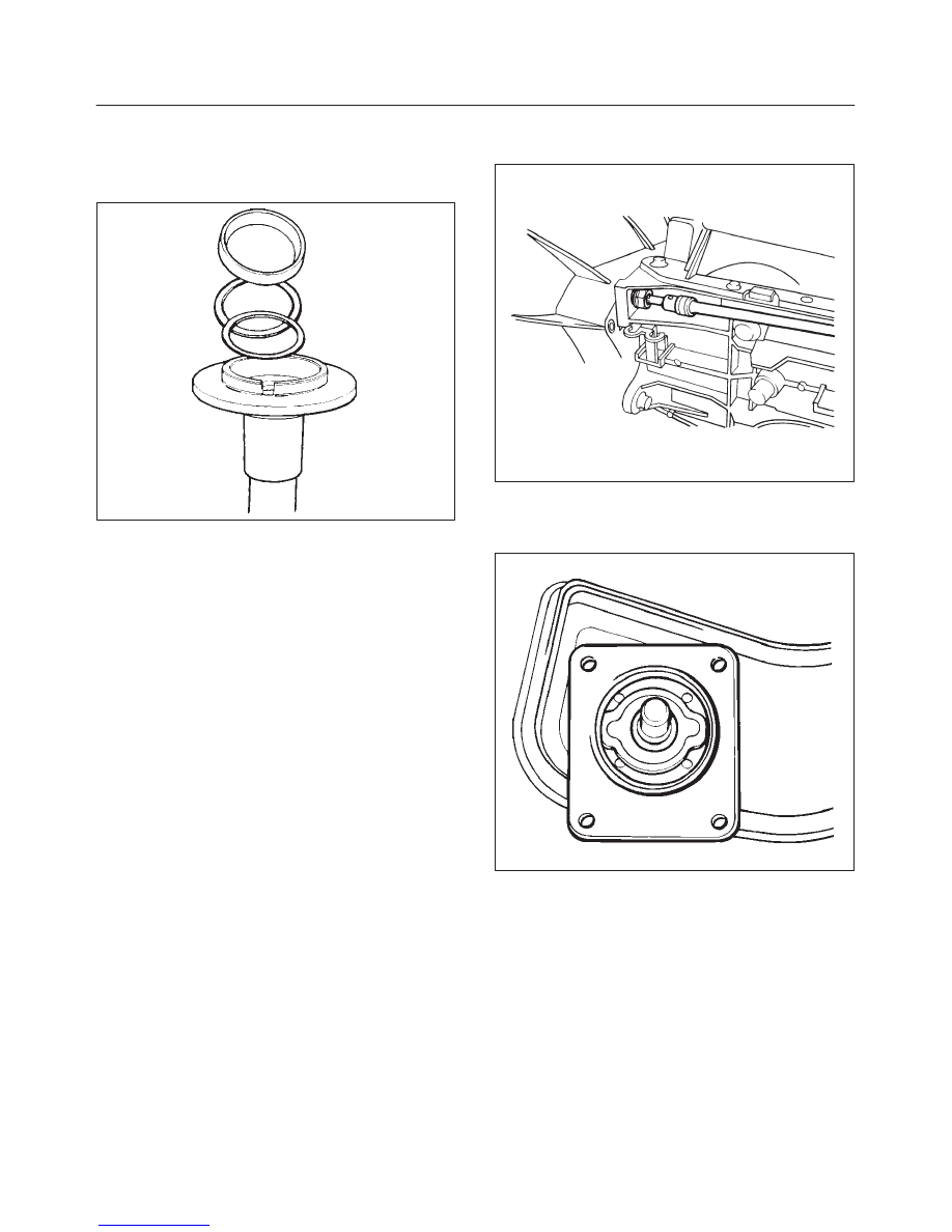
Remove the input bearing retainer.
f
Install the selected shim(s) (12) behind the input
bearing outer race(12) in the retainer.
If two shims are used, put the thinner one in first.
226RS135
f
Install the input shaft bearing retainer(12) against
the case.
Torque: 20 N·m (15 lb ft)
f
Recheck the input/mainshaft end play.
Change the shim again if end play is not zero
(
±
0.001 inch).
f
Apply a 1/8–inch(3 mm) bead of RTV sealant on the
sealing surface of the retainer.
f
Apply sealer to the threads of the four retainer bolts.
f
Install the input shaft bearing retainer(12) against
the case.
Torque: 20 N·m (15 lb ft)
24. Install the speedometer driven gear assembly.
25. Remove the transmission from the holding fixture.
26. Loosen the fill plug and fill with DEXRON
–III
Automatic Transmission Fluid.
27. Install the clutch housing to the case.
Torque: 76 N·m (56 lb ft)
220RS059
28. Install the clutch release bearing and shift fork.
29. Clean the sealing surface of the shift control lever and
inspect it for warpage.
235RS004
7B–82
MANUAL TRANSMISSION
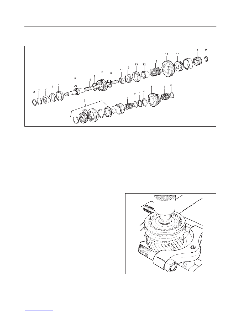
Mainshaft (TREMEC T5R)
Disassembled View
226RS136
Legend
(1) 3rd–4th Synchronizer Assembly (Spring,
Sleeve, Insert, & Hub), Blocking Ring, and 3rd
Gear
(2) 3rd Gear Needle Bearing and Spacer
(3) Snap Ring
(4) Thrust Washer
(5) 2nd Gear, Bearing and Spacer
(6) Spiral Retaining Ring
(7) Thrust Washer and 2nd Blocking Ring
Assembly (Inner Cone, Outer Cone Race &
2nd Blocking Ring)
(8) Spring, Reverse Sliding Gear, Insert
(9) 5th Driven Gear and Snap Ring
(10) Mainshaft Rear Bearing
(11) 1st Gear
(12) 1st Gear Bearing and Sleeve
(13) 1st Blocking Ring Assembly (Inner Cone, Outer
Cone Race, 1st Blocking Ring)
(14) Mainshaft (with 1–2 Hub)
Disassembly
1. 3rd–4th synchronizer assembly, blocking ring and 3rd
gear.
f
Scribe an alignment mark on both the 3–4
synchronizer hub and sleeve. Use these marks for
correct reassembly.
f
Using a hydraulic press and the bearing and gear
puller plate J–22912–01, remove the 3–4
synchronizer assembly(1), block ring(1) and the 3rd
gear(1).
226RS137
MANUAL TRANSMISSION
7B–83
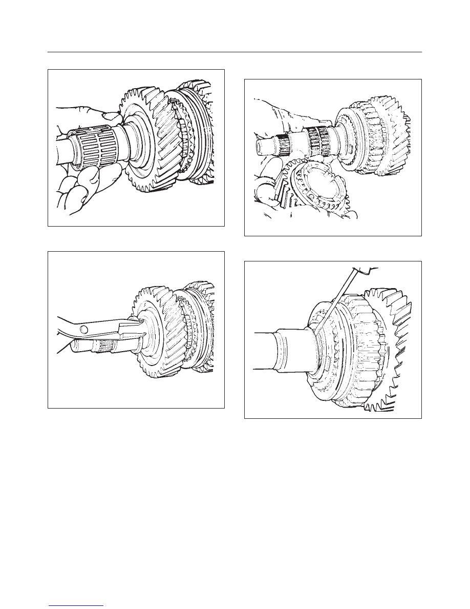
2. Remove needle bearing(2) and spacer(2).
226RW149
3. Second gear snap ring(3), using a pair of snap ring
pliers.
226RW150
4. Remove thrust washer(4).
5. Remove 2nd gear(5), bearing(5) and spacer(5).
226RS140
6. Remove spiral retaining ring, using a pocket
screwdriver.
226RS141
Нет комментариевНе стесняйтесь поделиться с нами вашим ценным мнением.
Текст