Isuzu Rodeo UE. Manual — part 123

5C–53
POWER–ASSISTED BRAKE SYSTEM
Main Data and Specifications (4
×
4 Model)
General Specifications
Type
Floating, pin slide
Pad dimension
33 cm
@
(5.11 in
@
)
Adjusting method
Self–adjusting
Piston diameter
41.3 mm (1.63 in)
Disc type
Ventilated
Disc thickness
18 mm (0.71 in)
Disc effective diameter
269.2 mm (10.60 in)
Torque Specifications
E05RW005
5C–54 POWER–ASSISTED BRAKE SYSTEM
Brake Lining
Brake Lining and Associated Parts
305RW001
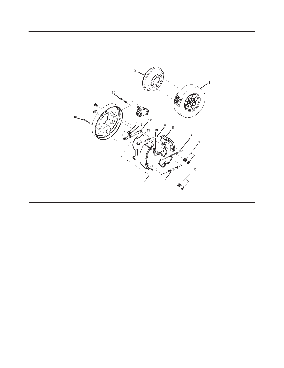
Legend
(1) Wheel and Tire Assembly
(2) Drum
(3) Hold-down Spring and Cup
(4) Hold-down Spring and Cups
(5) Lower Return Spring
(6) Upper (other) Return Spring
(7) Trailing Shoe Assembly with Parking Brake
Lever
(8) Leading Shoe Assembly with Upper (inner)
Return Spring
(9) Upper (inner) Return Spring
(10) Auto Adjuster Lever
(11) Parking Brake Lever
(12) Adjuster Assembly
(13) Wave Washer
(14) Retainer
(15) Hold-down Pin
(16) Hold-down Pin
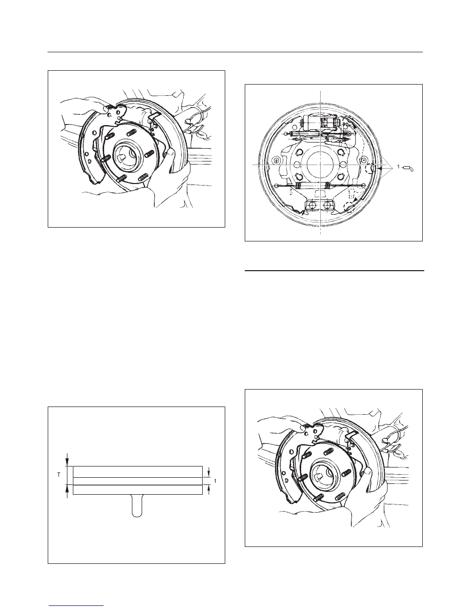
Removal
1. Raise the vehicle and support with suitable safety
stands.
2. Remove wheel and tire assembly (1).
f
Refer to “Wheel and Tires” in Wheel and Tire
System section.
3. Remove Drum (2).
f
If difficulty is encountered in removing the drum:
– Mark the position of the drum to the axle.
– Make sure the parking brake is released.
– Use a rubber mallet to tap gently on the outer rim of
the drum and/or around the inner drum. Be careful
to avoid damaging the drum.
4. Remove upper (other) return spring (6) and auto
adjuster lever.
5. Remove lower return spring (5).
6. Remove hold-down spring and cups (4) and
hold-down pin (15).
7. Remove adjuster assembly (12)
8. Remove leading shoe assembly (8) with upper (inner)
return spring (9).
5C–55
POWER–ASSISTED BRAKE SYSTEM
NOTE: Do not over stretch the return spring.
305RS003
9. Remove upper (inner) return spring (9).
10. Remove hold-down spring and cup (3) and hold-down
pin (16).
11. Remove Trailing shoe assembly (7) with parking
brake lever (16).
12. Remove parking brake cable from parking brake lever
(11).
13. Remove retainer (14), wave washer (13), and parking
brake lever (11).
Brake Lining Inspection
Check the shoe assemblies for wear by removing brake
drum.
Replace the shoe assemblies, if lining thickness is less
than 1.0 mm (0.039 in).
The shoe assemblies have a wear indicator that makes a
noise when the linings wear to a degree where
replacement required.
Minimum limit: 1.0 mm (0.039 in)
305RS001
Installation
1. Apply grease lightly to back place A.
305RW002
Legend
(1) Place A (3 portions for each side)
2. Install parking brake lever (11), wave washer (13),
and retainer (14).
3. Install trailing shoe assembly (7) with parking brake
lever (16).
4. Install the parking brake cable to parking brake lever
(11).
5. Install hold-down pin (16) and hold-down spring and
cup (3).
6. Install upper (inner) return spring (9).
7. Install leading shoe assembly (8) with upper (inner)
return spring (9).
NOTE: Do not over stretch the return spring.
305RS003
8. Install adjuster assembly (12).
9. Install hold-down pin (15) and hold-down spring and
cups (4).
5C–56 POWER–ASSISTED BRAKE SYSTEM
10. Install lower return spring (5).
f
Use brake spring tool.
11. Install auto adjuster lever (10).
12. Install upper (outer) return spring (6).
f
Use brake spring tool.
13. Install brake drum (2).
f
Adjust the brakes, refer to the “Drum Brake
Adjustment” in this section.
14. Install wheel and tire assembly (1).
f
Refer to “Wheels and Tires ” in wheel and Tire
System section.
Drum Brake Adjustment (4
×
2 Model)
NOTE: All brakes are self-adjusting. Brakes are adjusted
by repeated stepping on the brake pedal. (After stepping
on the pedal and releasing it, the rear auto adjuster, in the
rear brake, produces a clicking sound.
The same operation should be repeated until the sound
disappears.)
Take the following steps after overhauling the rear brake
assembly.
1. Move the parking brake handle to its fully released
position.
2. Parking cable must be loosened sufficiently. (Loosen
the adjust nut and the lock nut.)
3. Repeat stepping on the brake pedal firmly, and
releasing it until the clicking sound can no longer be
heard.
If the difference between the brake drum inside
diameter and diameter of the brake shoes is adjusted
to be 0,5 mm, the number of times for depressing the
brake pedal can be reduced.
4. Remove the drum. Measure the brake drum inside
diameter and diameter of the brake shoes.
Shoe clearance: 0.25-0.4 mm (0.0098-0.0157 in)
If incorrect, check the brake auto-adjusting system.
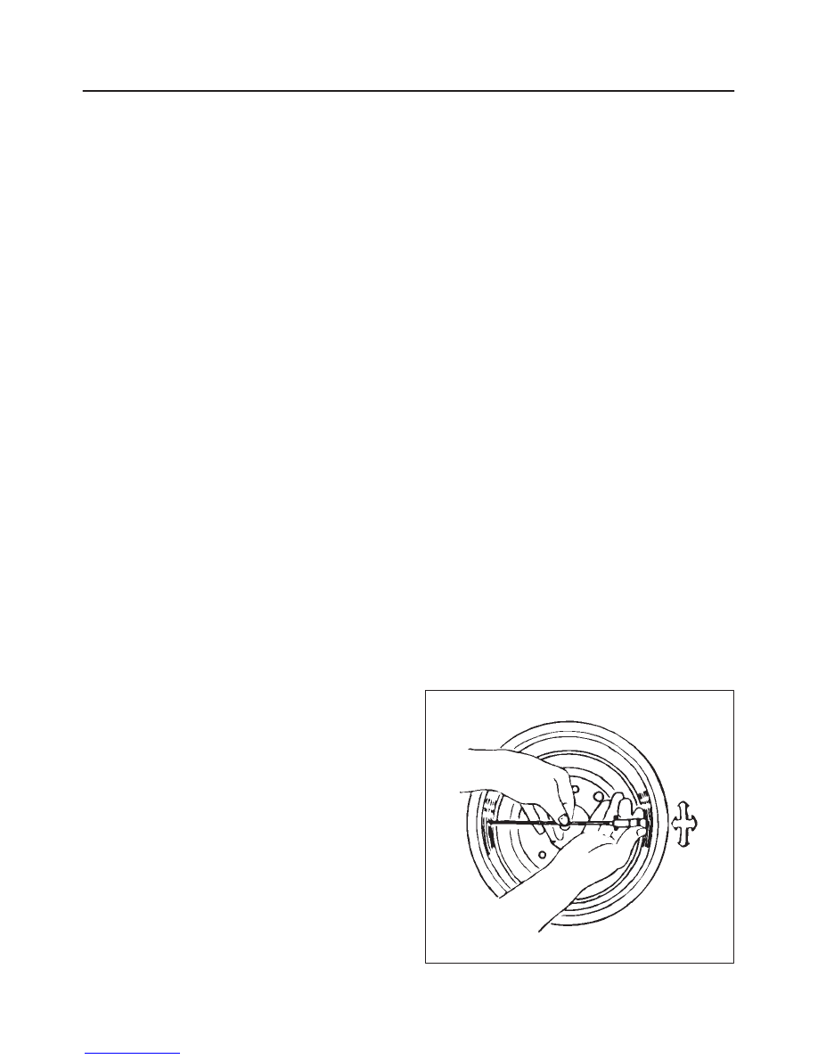
5. Rotate the adjust nut until all slack disappears from
the cable. Set the adjust nut.
6. Applying about 30 kg (66 lb) of force, pull the parking
brake handle to its fully set position three or four
times.
7. If the parking brake is properly adjusted, the travel
between the fully disengaged position and the fully
engaged position will be between 9 and 11 notches.
If the traveling range is not within these limits, again
repeat steps 1 through 5.
After adjusting has been done, check to see if the rear
wheel rotates smoothly without drag when turned by
hand.
Servicing The Brake Drum
Whenever the brake drums are removed, they should be
thoroughly cleaned and inspected for cracks, scores,
deep grooves and out-of-round.
Cracked, Scored or Grooved Drum
A cracked drum is unsafe for further service and must be
replaced.
Do not attempt to weld a cracked drum.
Smooth any slight scores. Heavy or extensive scoring will
cause excessive brake lining wear, and it will probably be
necessary to machine the drum braking surface.
If the brake linings are slightly worn and the drum is
grooved, the drum should be polished with fine emery
cloth but should not be machined. At this stage,
eliminating all the grooves in the drum and smoothing the
ridges on the lining would require the removal of too much
metal and lining. If left alone, the grooves and ridges
match and satisfactory service can be obtained. If brake
linings are to be replaced, a grooved drum should be
machined. A grooved drum, if used with a new lining, will
not only wear the lining, but will make it difficult, it not
impossible, to obtain efficient brake performance.
Out-Of-Round Drum
An out-of-round drum makes accurate brake shoe
adjustment impossible and is likely to cause excessive
wear to other parts of the brake mechanism due to its
eccentric action. An out-of-round drum can also cause
severe and irregular tire tread wear as well as a pulsing
brake pedal. When the braking surface of a brake drum
exceeds the specification limit of 0.15 mm (0.006 in) in
out-of-round, the drum should be machined to true up the
braking surface. Out-of-round can be accurately
measured with an inside micrometer fitted with proper
extension rods. When measuring a drum for out-of-round
and wear, take measurements at the open and closed
edges of machines surfaces and at right angles to each
other.
Maximum out-of-round: 0.15 mm (0.006 in)
420RS034
Нет комментариевНе стесняйтесь поделиться с нами вашим ценным мнением.
Текст