Isuzu Rodeo UE. Manual — part 289
6A–69
ENGINE MECHANICAL (6VD1 3.2L)
7. Remove oil gallery (7).
8. Remove piston and connecting rod assembly (8).
Refer to “Piston, Piston Ring and Connecting Rod” in
this manual.
9. Remove flywheel (9).
10. Remove rear oil seal retainer (10).
11. Remove main bearing cap (11).
12. Remove crankshaft (12).
Inspection and Repair
1. Crankshaft
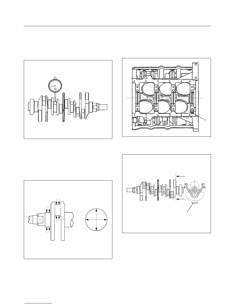
Set the dial indicator as shown in the illustration and
measure the crankshaft thrust clearance. If the thrust
clearance exceeds the specified limit, replace the
thrust bearings as a set.
Thrust Clearance
Standard : 0.06 mm–0.24 mm
(0.0024 in–0.0094 in)
Limit : 0.30 mm (0.0118 in)
015RS003
Main Bearing Clearance
1. Remove the bearing caps and measure the oil
clearance.
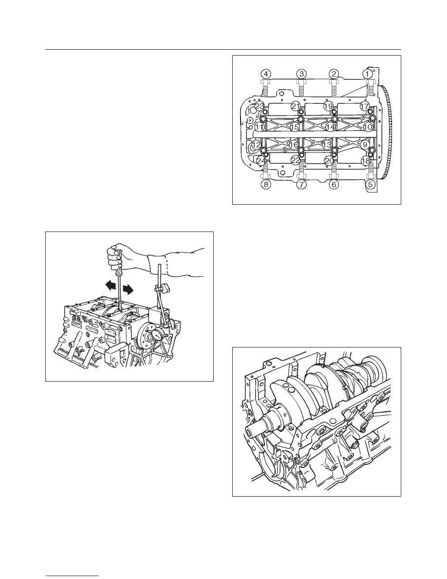
2. Remove the main bearing cap fixing bolts in the
sequence shown in the illustration.
Arrange the removed main bearing caps in the
cylinder number order.
Remove the main bearings.
015RS004
3. Remove the crankshaft.
Remove the main bearings.
4. Clean the upper and lower bearings as well as the
crankshaft main journal.
5. Check the bearings for damage or excessive wear.
The bearings must be replaced as a set if damage or
excessive wear is discovered during inspection.
6. Set the upper bearings and the thrust washers to their
original positions.
Carefully install the crankshaft.
7. Set the lower bearings to the bearing cap original
position.
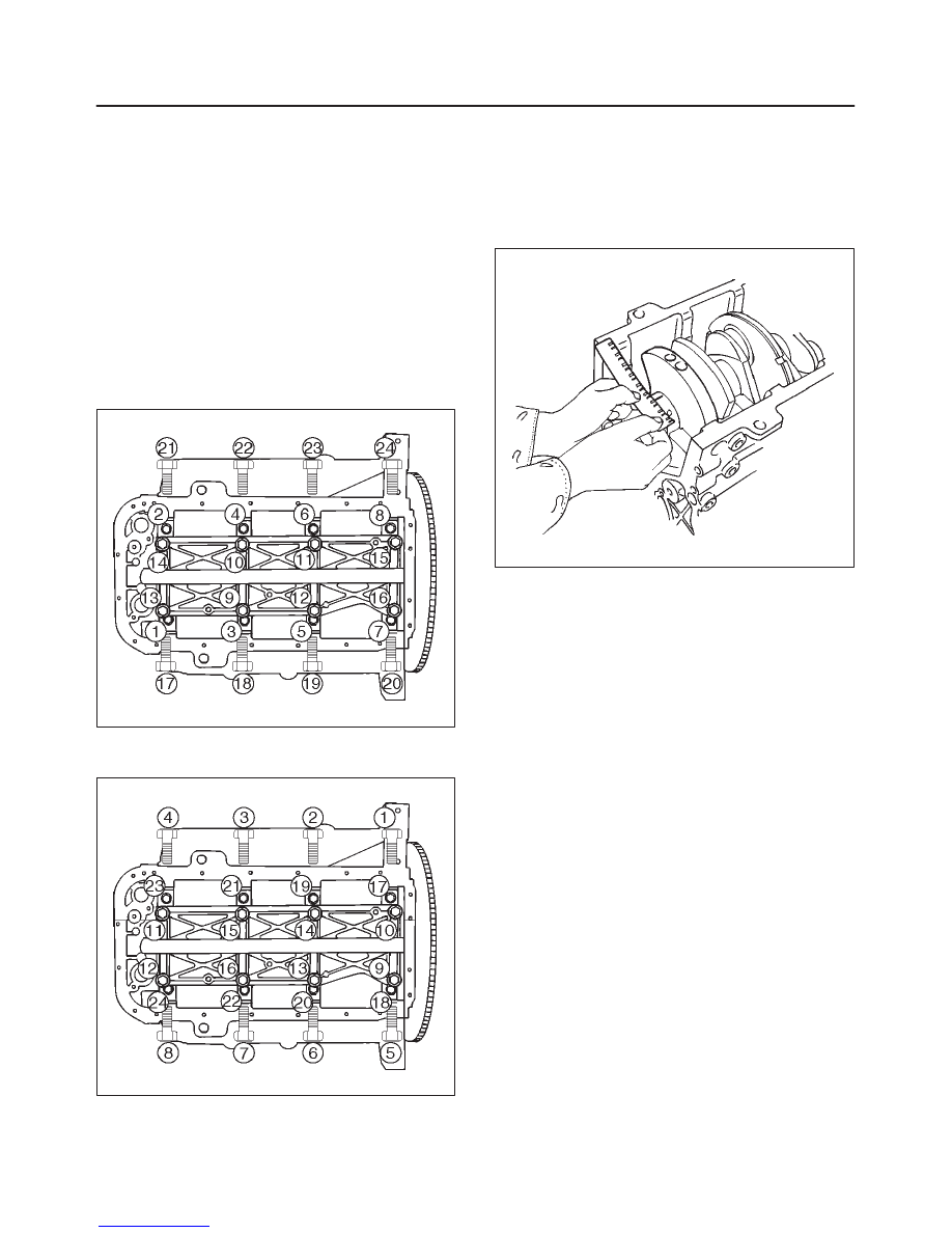
8. Apply plastigage to the crankshaft journal unit as
shown in the illustration.
NOTE: Do not set the plastigage on the oil hole.
015RS005
6A–70
ENGINE MECHANICAL (6VD1 3.2L)
9. Install main bearing caps, oil gallery and crank case
bolts in the order shown, and tighten each bolt to the
specified torque.
NOTE: Do not apply engine oil to the crank case side
bolts.
Main bearing cap bolts.
Torque: 39 N·m (29lb ft)
Oil gallery fixing bolts.
Torque:
1st step: 29 N·m (21 lb ft)
2nd step 55
°
∼
65
°
Crank case side bolts
Torque : 39 N·m (29lb ft)
NOTE: Do not allow the crankshaft to rotate.
015RS006
10. Remove the main bearing caps in the sequence
shown in the illustration.
015RS004
11. Measure the plastigage width and determine the oil
clearance. If the oil clearance exceeds the specified
limit, replace the main bearings as a set and/or
replace the crankshaft.
Standard : 0.019 mm–0.043 mm
(0.0007 in–0.0017 in)
Limit : 0.08 mm (0.0031 in)
015RS008
12. Clean the plastigage from the bearings and the
crankshaft.
Remove the crankshaft and the bearings.
Crankshaft (12) Inspection
Inspect the surface of the crankshaft journal and crank
pins for excessive wear and damage. Inspect the oil seal
fitting surfaces for excessive wear and damage. Inspect
the oil ports for obstructions.
6A–71
ENGINE MECHANICAL (6VD1 3.2L)
Inspection and Repair
1. Carefully set the crankshaft on the V–blocks. Slowly
rotate the crankshaft and measure the runout. If the
crankshaft runout exceeds the specified limit, the
crankshaft must be replaced.
Runout : 0.04 mm (0.0016 in)
015RS007
2. Measure the diameter and the uneven wear of main
journal and crank pin. If the crankshaft wear exceeds
the specified limit, crankshaft must be replaced.
Main journal diameter : 63.918 mm–63.933 mm
(2.5165 in–2.5170 in)
Crank pin diameter : 53.922 mm–53.937 mm
(2.1229 in.–2.1235 in.)
Uneven wear limit : 0.005 mm (0.0002 in)
015RS009
Crankshaft Bearing Selection
When installing new crankshaft bearings or replacing
bearings, refer to the selection table below. Select and
install the new crankshaft bearings, paying close
attention to the cylinder block journal hole.
1. Diameter size mark (1) and the crankshaft journal.
015RS010
2. Diameter size mark (1).
The diameter size marks are stamped on the No.1
crankshaft balancer as shown in the illustration.
015RS011
NOTE: Take care to ensure the bearings are positioned
correctly.
6A–72
ENGINE MECHANICAL (6VD1 3.2L)
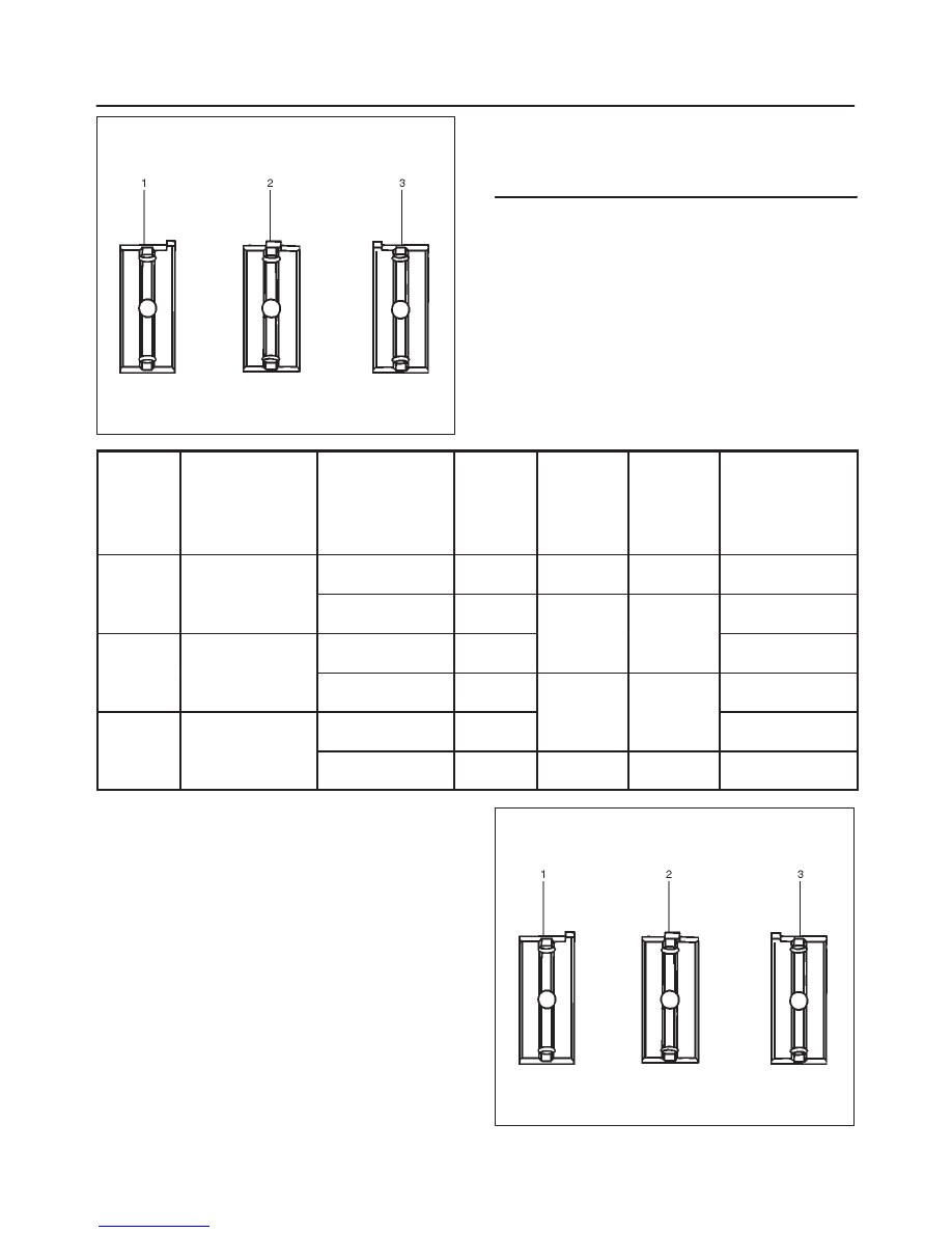
015RS012
Legend
(1) Number 1 and 4 main bearing upper and lower
(2) Number 2 and 3 main bearing upper
(3) Number 2 and 3 main bearing lower
1 Size
Mark
Main Bearing
Bore Diameter
Crank Shaft Main
Journal Diameter
2 Size
Mark
Crank
Shaft
Bearing
Size Mark
(Upper
Side)
Crank
Shaft
Bearing
Size Mark
(Lower
Side)
Oil Clearance
(Reference)
1
68.994-69.000
63.918-63.925
(2.5165-2.5167)
2
Blue
Blue
0.030-0.049
(0.0012-0.0019)
1
(2.7163-2.7165)
63.926-63.933
(2.5168-2.5170)
1
Brown
Brown
0.028-0.047
(0.0011-0.0019)
2
68.987-68.993
63.918-63.925
(2.5165-2.5167)
2
Brown
Brown
0.029-0.048
(0.0011-0.0019)
2
(2.7160-2.7163)
63.926-63.933
(2.5168-2.5170)
1
Green
Green
0.027-0.046
(0.0011-0.0018)
3
68.980-68.986
63.918-63.925
(2.5165-2.5167)
2
Green
Green
0.028-0.047
(0.0011-0.0019)
3
(2.7157-2.7160)
63.926-63.933
(2.5168-2.5170)
1
Yellow
Yellow
0.026-0.045
(0.0010-0.0018)
Reassembly
1. Crankshaft (12)
f
Install the main bearings to the cylinder block and
the main bearing caps.
f
Be sure that they are positioned correctly.
f
Apply new engine oil to the upper and lower main
bearing faces.
NOTE: Do not apply engine oil to the main bearing back
faces.
015RS012
Нет комментариевНе стесняйтесь поделиться с нами вашим ценным мнением.
Текст