Isuzu Rodeo UE. Manual — part 423

6E2–447
RODEO 6VD1 3.2L ENGINE DRIVEABILITY AND EMISSIONS
Lack of Power, Sluggish or Spongy
1. OBD system check.
2. Fuel system diagnosis.
3. Ignition system.
4. Knock sensor.
5. EGR operation.
6. EGR system check.
Refer to
Exhaust System in
Engine Exhaust, TCC
Operation, Calibration
ID/Service Bulletins
Detonation/Spark Knock
1. OBD system check.
2. Transmission range switch.
3. EGR operation.
4. EGR system check.
5. TCC operation.
6. Fuel system diagnosis.
7. Ignition system.
8. Knock sensor.
TCC operation, Cooling System,
Ignition System Check,
Calibration ID/Service Bulletins
Hesitation, Sag, Stumble
1. OBD system check.
2. TP.
3. MAP output check.
4. Fuel system diagnosis.
5. Fuel injector and fuel injector
balance test.
6. EVAP emission canister purge
valve.
7. Ignition system.
EGR Operation, EGR System
Check, Generator Output
Voltage (refer to
Chassis
Electrical), Calibration
ID/Service Bulletins, Ignition
System Check
Cuts Out, Misses
1. OBD system check.
2. Cylinder balance test.
Ignition System Check
Rough, Unstable, or Incorrect Idle,
Stalling
1. OBD system check.
2. Fuel injector and fuel injector
balance test.
3. EVAP emission canister purge
valve check.
4. Ignition system.
5. IAC operation.
6. EGR operation.
MAP Output Check, Throttle
Linkage, IAC System Check,
EGR System Check, A/C Clutch
Control Circuit Diagnosis,
Crankcase Ventilation System,
Calibration ID/Service Bulletins,
Generator Output Voltage (refer
to
Chassis Electrical), Exhaust
Diagnosis
Poor Fuel Economy
1. OBD system check.
2. Careful visual/physical inspection.
3. Ignition system.
4. Cooling system.
TCC Operation, Exhaust
System (refer to
Engine
Exhaust)
Engine Cranks But Will Not Run
1. OBD system check.
Fuel System Electrical
Diagnosis, Fuel System
Diagnosis, Fuel Injector and
Fuel Injector Balance Test.
Excessive Exhaust Emissions or
Odors
1. OBD system check.
2. Emission test.
3. Cooling system.
4. Fuel system diagnosis.
5. Fuel injector and fuel injector
balance test.
6. EVAP emission canister purge
valve.
7. Crankcase ventilation system.
8. Ignition system.
9. MAP output check.
EGR System Check, Exhaust
Diagnosis, Calibration
ID/Service Bulletins

6E2–448
RODEO 6VD1 3.2L ENGINE DRIVEABILITY AND EMISSIONS
Dieseling, Run-On
1. OBD system check.
2. Careful visual/physical inspection.
3. Fuel system diagnosis.
—
Backfire
1. OBD system check.
2. Ignition system.
3. Fuel system diagnosis.
4. Fuel injector and fuel injector
balance test.
5. EGR operation, EGR system
check.
Exhaust System Diagnosis,
Intake Casting Flash, Ignition
System Check
Misfire
1. OBD system check.
2. Ignition system.
3. Fuel system diagnosis.
4. Fuel injector and fuel injector
balance test.
Vibrations, Transmission,
Driveshaft and Axle
Catalyst Monitor
1. OBD system check.
2. Careful visual/physical inspection.
3. Heated oxygen sensors.
Exhaust System
Fuel Trim
1. OBD system check.
2. Careful visual/physical inspection.
3. Fuel system diagnosis.
4. Heated oxygen sensors, MAF
sensors.
Exhaust System Intake Air
System
Evaporative Emissions
1. OBD system check.
2. Careful visual/physical inspection.
3. Fuel system diagnosis.
—
Heated Oxygen Sensors
1. OBD system check.
2. Careful visual/physical inspection.
Exhaust System
6E2–449
RODEO 6VD1 3.2L ENGINE DRIVEABILITY AND EMISSIONS
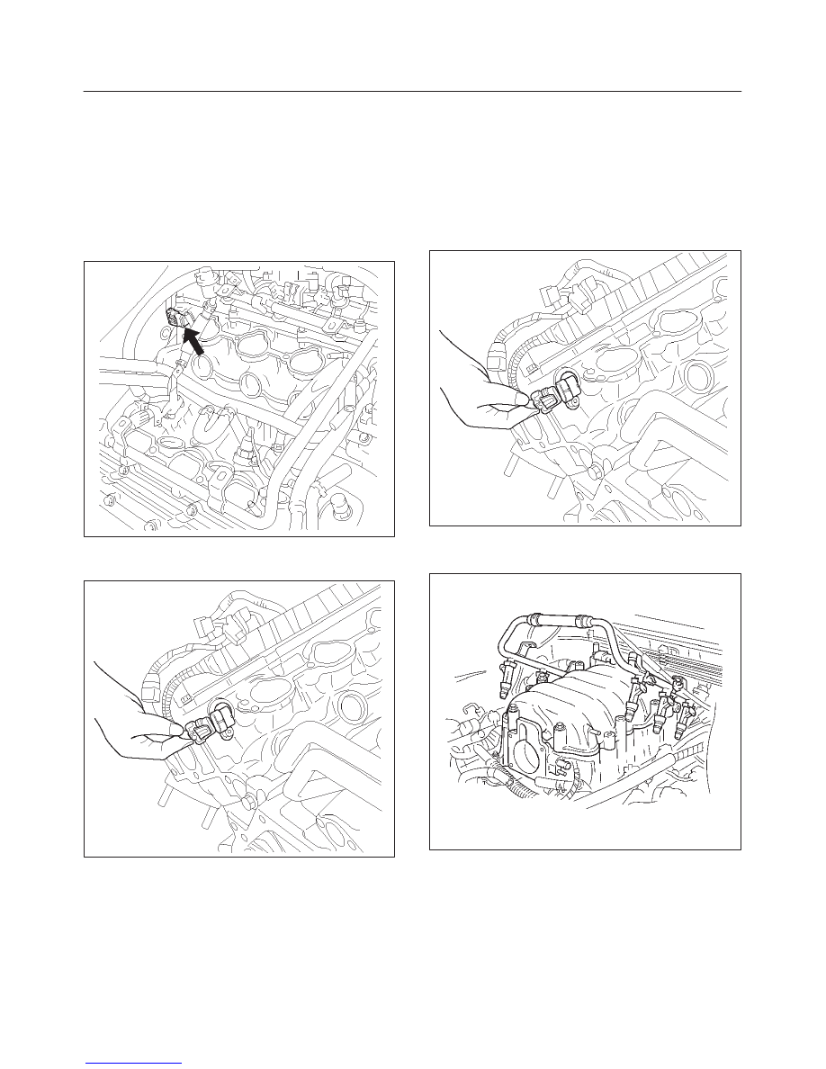
On-Vehicle Service Camshaft
Position (CMP) Sensor
Removal Procedure
1. Disconnect the negative battery cable.
2. Remove the engine cover.
3. Remove the common chamber assembly.
Refer to Common Chamber in Engine Mechanical.
014RW120
4. Disconnect the electrical connector to the CMP
sensor.
014RV053
5. Remove the CMP retaining bolt from the side of left
cylinder head.
6. Remove the CMP sensor from the cylinder head.
Inspection Procedure
1. Inspect the sensor O-ring for cracks or leaks.
2. Replace the O-ring if it is worn or damaged.
3. Lubricate the new O-ring with engine oil.
4. Install the lubricated O-ring.
Installation Procedure
1. Install the CMP sensor in the cylinder head.
2. Install the CMP sensor retaining bolt.
Tighten
f
Tighten the retaining screw to 9 N·m (78 lb in.).
3. Connect the electrical connector to the CMP sensor.
014RV053
4. Install the common chamber assembly.
Refer to Common Chamber in Engine Mechanical.
014RW106
5. Install the engine cover.
6. Connect the negative battery cable.
6E2–450
RODEO 6VD1 3.2L ENGINE DRIVEABILITY AND EMISSIONS
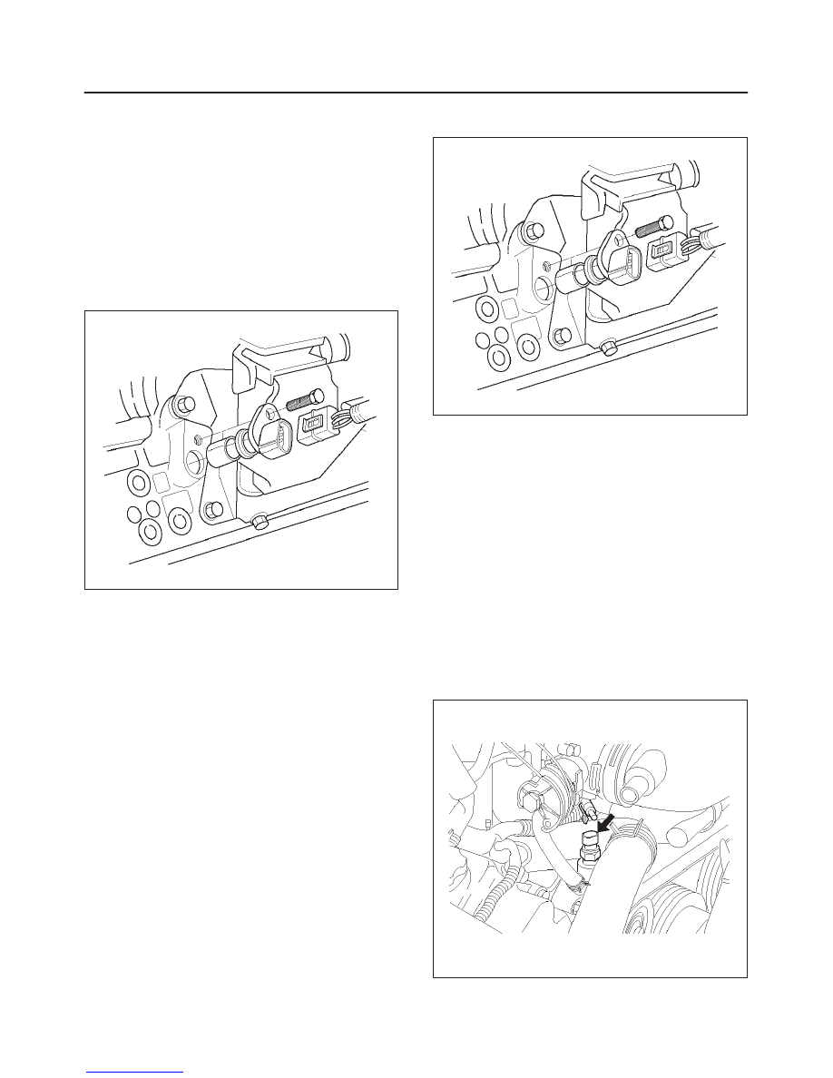
Crankshaft Position (CKP)
Sensor
Removal Procedure
1. Disconnect the negative battery cable.
2. Disconnect the electrical connector to the CKP
sensor.
3. Remove one bolt and the CKP sensor from the right
side of the engine block, just behind the mount.
NOTE: Use caution to avoid any hot oil that might drip
out.
TS22909
Inspection Procedure
1. Inspect the sensor O-ring for cracks or leaks.
2. Replace the O-ring if it is worn or damaged.
3. Lubricate the new O-ring with engine oil.
4. Install the lubricated O-ring.
Installation Procedure
1. Install the CKP sensor in the engine block.
2. Install the CKP sensor mounting bolt.
Tighten
f
Tighten the mounting bolt to 9 N·m (78 lb in.).
TS22909
3. Connect the electrical connector to the CKP sensor.
4. Connect the negative battery cable.
Engine Coolant Temperature
(ECT) Sensor
Removal Procedure
NOTE: Care must be taken when handling the engine
coolant temperature (ECT) sensor. Damage to the ECT
sensor will affect proper operation of the fuel injection
system.
1. Disconnect the negative battery cable.
2. Drain the radiator coolant. Refer to
Draining and
Refilling Cooling System in Engine Cooling.
3. Disconnect the electrical connector.
014RW127
Нет комментариевНе стесняйтесь поделиться с нами вашим ценным мнением.
Текст