Isuzu Rodeo UE. Manual — part 359

6E2–191
RODEO 6VD1 3.2L ENGINE DRIVEABILITY AND EMISSIONS
DTC P0151 — HO2S Circuit Low Voltage Bank 2 Sensor 1
(Cont'd)
Step
No
Yes
Value(s)
Action
7
Repair the short between the high and low circuits.
Is the action complete?
—
Verify repair
—
8
1. Ignition “OFF.”
2. Reconnect the PCM, leave HO2S 1 disconnected.
3. Ignition “ON.”
Does the Tech 2 indicate Bank 2 HO2S 1 voltage near
the specified value?
425-475 mV
Refer to
Diagnostic
Aids
Go to
Step 9
9
Replace the PCM.
IMPORTANT: The replacement PCM must be
programmed. Refer to
On-Vehicle Service in
Powertrain Control Module and Sensors for
procedures.
And also refer to latest service bulletin.
Check to see if the Latest software is released or not.
And then Down Load the LATEST PROGRAMMED
SOFTWARE to the replacement PCM.
Is the action complete?
—
Verify repair
—
6E2–192
RODEO 6VD1 3.2L ENGINE DRIVEABILITY AND EMISSIONS
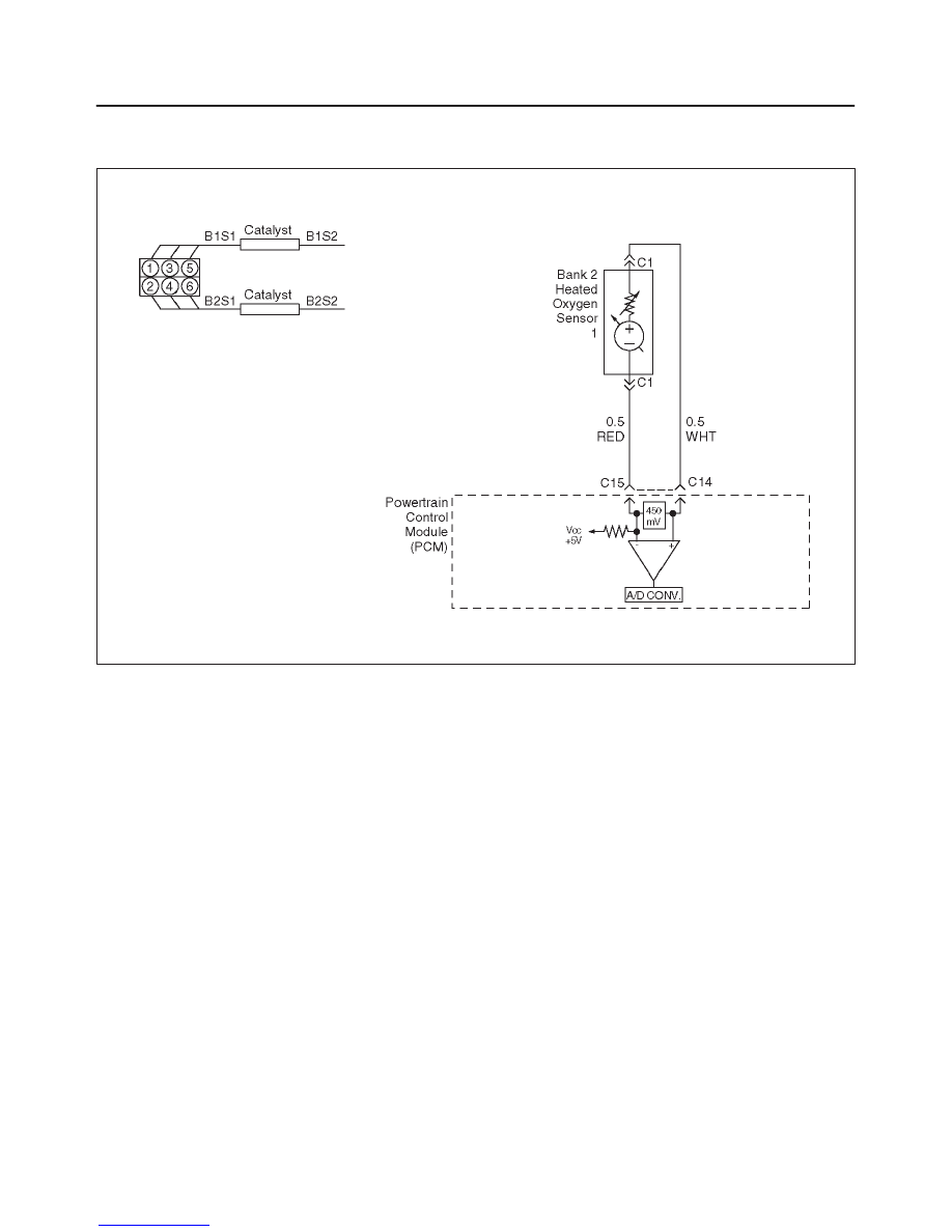
Diagnostic Trouble Code (DTC) P0152 HO2S Circuit High Voltage Bank 2
Sensor 1
D06RW083
Circuit Description
The powertrain control module (PCM) supplies a bias
voltage of about 450 mV between the heated oxygen
sensor (HO2S) signal high and signal low circuits. When
measured with a 10 megaohm digital voltmeter, this may
display as low as 320 mV. The oxygen sensor varies the
voltage within a range of about 1000 mV when the
exhaust is rich, down through about 10 mV when exhaust
is lean. The PCM constantly monitors the HO2S signal
during “closed loop” operation and compensates for a rich
or lean condition by decreasing or increasing the injector
pulse width as necessary. If the Bank 2 HO2S 1 voltage
remains excessively high for an extended period of time,
DTC P0152 will be set.
Conditions for Setting the DTC
f
No related DTCs.
f
The engine is operating in “closed loop.”
f
The engine coolant temperature is above 60
°
C
(140
°
F).
f
“Closed loop” commanded air/fuel ratio between 14.5
and 14.8.
f
Throttle angle between 3% and 19%.
f
Bank 2 HO2S 1 signal voltage remains above 952 mV
during normal “closed loop” operation for a total of 77
seconds over a 90-second period.
OR
f
Bank 2 HO2S 1 signal voltage remains above 500 mV
during deceleration fuel cutoff mode operation for up to
3 seconds.
Action Taken When the DTC Sets
f
The PCM will illuminate the malfunction indicator lamp
(MIL) the first time the fault is detected.
f
The PCM will store conditions which were present
when the DTC was set as Freeze Frame and in the
Failure Records data.
f
“Open loop” fuel control will be in effect.
Conditions for Clearing the MIL/DTC
f
The PCM will turn the MIL “OFF” on the third
consecutive trip cycle during which the diagnostic has
been run and the fault condition is no longer present.
f
A history DTC P0152 will clear after 40 consecutive
warm-up cycles have occurred without a fault.
f
DTC P0152 can be cleared by using the Tech 2 “Clear
Info” function or by disconnecting the PCM battery
feed.
Diagnostic Aids
Check for the following conditions:
f
Fuel pressure – The system will go rich if pressure is
too high. The PCM can compensate for some
increase. However, if fuel pressure is too high, a DTC
P0152 may be set. Refer to
Fuel System Diagnosis.
f
Rich injector(s) – Perform “Injector Balance Test.”

6E2–193
RODEO 6VD1 3.2L ENGINE DRIVEABILITY AND EMISSIONS
f
Leaking injector – Refer to
Fuel System Diagnosis.
f
Evaporative emissions (EVAP) system – Check the
canister for fuel saturation. If the canister is full of fuel,
check EVAP control system components and hoses.
Refer to
Evaporative Emission (EVAP) Control
System.
f
MAF sensor – The system can go rich if the MAF
sensor signal indicates an engine airflow
measurement that is not correct Disconnect the MAF
sensor to see if rich condition is corrected. If so,
replace MAF sensor.
f
Check for leaking fuel pressure regulator diaphragm by
checking vacuum line to regulator for the presence of
fuel. There should be no fuel in the vacuum line.
f
TP sensor – An intermittent TP sensor output will
cause the system to go rich, due to a false indication
of the engine accelerating.
f
Shorted Heated Oxygen Sensor (HO2S)– If the HO2S
is internally shorted, the HO2S voltage displayed on
the Tech 2 will be over 1 volt. Try disconnecting the
affected HO2S with the key “ON,” engine “OFF.” If the
displayed HO2S voltage changes from over 1000 mV
to around 450 mV, replace the HO2S. Silicon
contamination of the HO2S can cause a high HO2S
voltage to be indicated. This condition is indicated by
powdery white deposit on the portion of the HO2S
exposed to the exhaust stream. If contamination is
noticed, replace the affected HO2S.
f
Open HO2S Signal Circuit of Faulty HO2S– A poor
connection or open in the HO2S signal circuit can
cause the DTC to set during deceleration fuel mode.
An HO2S which is faulty and not allowing a full voltage
switch between the rich and lean thresholds can also
cause the condition. Operate the vehicle while
monitoring the HO2S voltage with a Tech 2. If the
HO2S is voltage limited within a range between 300
mV to 600 mV, check the HO2S signal circuit wiring
and associated terminal connections.
f
If none of the above conditions are present, replace the
affected HO2S.
Test Description
Number(s) below refer to the step number(s) on the
Diagnostic Chart.
3. DTC P0152 failing during deceleration fuel cutoff
mode operation may indicate a condition described
in the “Diagnostic Aids” above. If the DTC P0152
test passes while the Failure Records conditions are
being duplicated, an intermittent condition is
indicated.
Reviewing the Failure Records vehicle mileage since the
diagnostic test last failed may help determine how often
the condition that caused the DTC to be set occurs. This
may assist in diagnosing the condition.
DTC P0152 – HO2S Circuit High Voltage Bank 2 Sensor 1
Step
Action
Value(s)
Yes
No
1
Was the “On-Board Diagnostic (OBD) System Check”
performed?
—
Go to
Step 2
Go to
OBD
System
Check
2
1. Install the Tech 2.
2. Engine is at operating temperature.
3. Operate the vehicle within the parameters specified
under “Conditions for Setting the DTC” criteria
included in Diagnostic Support.
4. Using a Tech 2, monitor Bank 2 HO2S 1 voltage.
Does the Bank 2 HO2S 1 voltage remain above the
specified value?
952 mV (500
mV in
deceleration
fuel cut-off
mode)
Go to
Step 4
Go to
Step 3
3
1. Ignition “ON.”
2. Review and record Tech 2 Failure Records data.
3. Operate the vehicle within Failure Records
conditions as noted.
4. Using a Tech 2, monitor “DTC” info for DTC P0152
until the DTC P0152 test runs.
5. Note the test result.
Does the Tech 2 indicate DTC P0152 failed this
ignition?
—
Go to
Step 4
Refer to
Diagnostic
Aids
4
1. Ignition “OFF.”
2. Disconnect Bank 2 HO2S 1.
3. Ignition “ON.”
4. At HO2S Bank 2 Sensor 1 connector (PCM side)
use a DVM to measure voltages at the high and low
signal terminals.
Are the voltages in the specified range?
3-4 V
Go to
Step 5
Go to
Step 6

6E2–194
RODEO 6VD1 3.2L ENGINE DRIVEABILITY AND EMISSIONS
DTC P0152 – HO2S Circuit High Voltage Bank 2 Sensor 1
(Cont'd)
Step
No
Yes
Value(s)
Action
5
Repair short to voltage in signal circuit.
Is the action complete?
—
Verify repair
—
6
1. Ignition “ON,” engine“OFF.”
2. At Bank 2 HO2S 1 connector (PCM side) jumper
both the HO2S high and low signal circuits (PCM
side) to ground.
3. Using a Tech 2, monitor Bank 2 HO2S 1 voltage.
Is Bank 2 HO2S 1 voltage below the specified value?
10 mV
Go to
Step 7
Go to
Step 8
7
1. Disconnect the jumpers to ground from Bank 2
HO2S 1 PCM-side connector.
2. With the HO2S 1 connector disconnected, monitor
Bank 2 HO2S 1 voltage.
Is the Bank 2 HO2S 1 voltage between the specified
values?
425-475 mV
Refer to
Diagnostic
Aids
Go to
Step 8
8
Replace the PCM.
IMPORTANT: The replacement PCM must be
programmed. Refer to
On-Vehicle Service in
Powertrain Control Module and Sensors for
procedures.
And also refer to latest service bulletin.
Check to see if the Latest software is released or not.
And then Down Load the LATEST PROGRAMMED
SOFTWARE to the replacement PCM.
Is the action complete?
—
Verify repair
—
Нет комментариевНе стесняйтесь поделиться с нами вашим ценным мнением.
Текст