Isuzu Rodeo UE. Manual — part 100
5A–23
BRAKE CONTROL SYSTEM
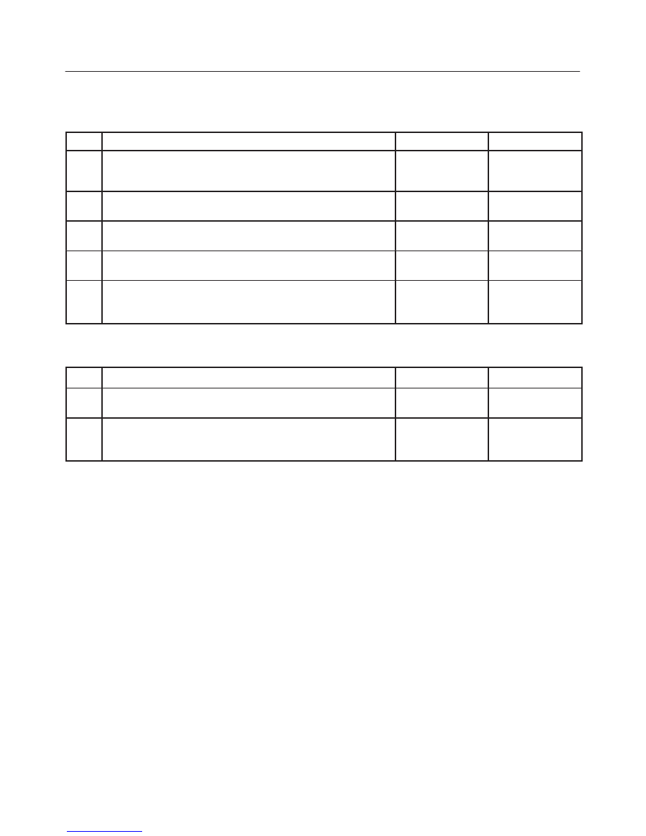
Basic Inspection Procedure
1. Basic Inspection of Service Brake
Step
Action
Yes
No
1
Is the fluid level normal?
Go to Step 2
Replenish with
fluid
Go to Step 2
2
Does fluid leak?
Repair
Go to Step 3
Go to Step 3
3
Is the booster function normal?
Go to Step 4
Repair
Go to Step 4
4
Is the pad and rotor normal?
Go to Step 5
Repair
Go to Step 5
5
Reconnect all components. Ensure all component are properly
mounted.
Was this step finished?
Finished
Go to Step 5
2. Ground Inspection
Step
Action
Yes
No
1
Does ABS—related ground points normally?
Go to Step 2
Repair
Go to Step 2
2
Reconnect all components. Ensure all component are properly
mounted.
Was this step finished?
Finished
Go to Step 2
5A–24
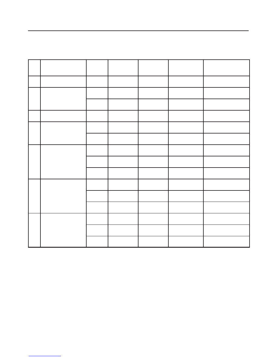
BRAKE CONTROL SYSTEM
EHCU Connector Pin-out Checks
f
Disconnect Electronic Hydraulic Control Module.
f
Perform checks with high impedance digital
multimeter J-39200 or equivalent.
No.
Circuit to be Tested
Ignition
Switch
Position
Multimeter
Scale/Range
Measure be-
tween Pin
Number
Nominal Value
Note
1
Power supply
OFF
20DCV
1 (C–5)
2 (C–5)
11.5V to 14.5V
2
Ignition enable
OFF
20DCV
1 (C–4)
7 (C–4)
0V to 0.1V
ON
20DCV
1 (C–4)
7 (C–4)
11.5V to 14.5V
3
Stoplight switch
OFF
20DCV
13 (C–4)
7 (C–4)
10.5V to 14.5V
Press brake pedal
4
Ground connection
OFF
200
W
7 (C–4)
Ground
Less than 2
W
OFF
1
W
2 (C–5)
Ground
Less than 0.2
W
5
FL speed sensor
OFF
2k
W
2 (C–4)
10 (C–4)
2.0k
W
to 2.8k
W
Internal Resistance
OFF
200k
W
2 (C–4)
7 (C–4)
more than
100k
W
Insulation Resistance
OFF
200mACV
2 (C–4)
10 (C–4)
more than
200mV
Turn wheel at 1RPS
6
FR speed sensor
OFF
2k
W
3 (C–4)
11 (C–4)
2.0k
W
to 2.8k
W
Internal Resistance
OFF
200k
W
3 (C–4)
7 (C–4)
more than
100k
W
Insulation Resistance
OFF
200mACV
3 (C–4)
11 (C–4)
more than
200mV
Turn wheel at 1RPS
7
RR speed sensor
OFF
2k
W
4 (C–4)
12 (C–4)
1.2k
W
to 2.0k
W
Internal Resistance
OFF
200k
W
4 (C–4)
7 (C–4)
more than
100k
W
Insulation Resistance
OFF
200mACV
4 (C–4)
12 (C–4)
more than
200mV
Turn wheel at 1RPS

5A–25
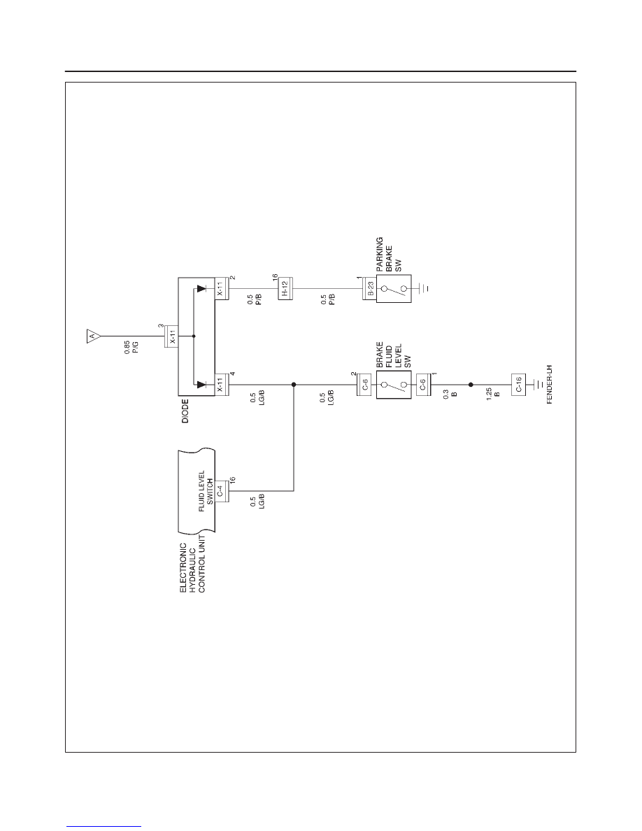
BRAKE CONTROL SYSTEM
Circuit Diagram
D08RX108
5A–26
BRAKE CONTROL SYSTEM
D08RX110
Нет комментариевНе стесняйтесь поделиться с нами вашим ценным мнением.
Текст