Isuzu Rodeo UE. Manual — part 151
6C–11
ENGINE FUEL (X22SE 2.2L)
Removal
CAUTION: When repair to the fuel system has been
completed, start engine and check the fuel system
for loose connection or leakage. For the fuel system
diagnosis, see Section “Driveability and Emission”.
1. Disconnect battery ground cable.
2. Loosen fuel filler cap.
3. Support underneath of the fuel tank protector (15)
with a lifter.
4. Disconnect evaporative fuel hose (3) at the canister.
5. Disconnect fuel feed hose (17) and fuel return hose
(18) near the fuel filter.
NOTE: Plug both ends of the fuel hoses to prevent fuel
leakage.
6. Disconnect air breather hose (4) and fuel filler hose
(5) at the fuel filler neck.
NOTE: Cover fuel hose to prevent any dust entering.
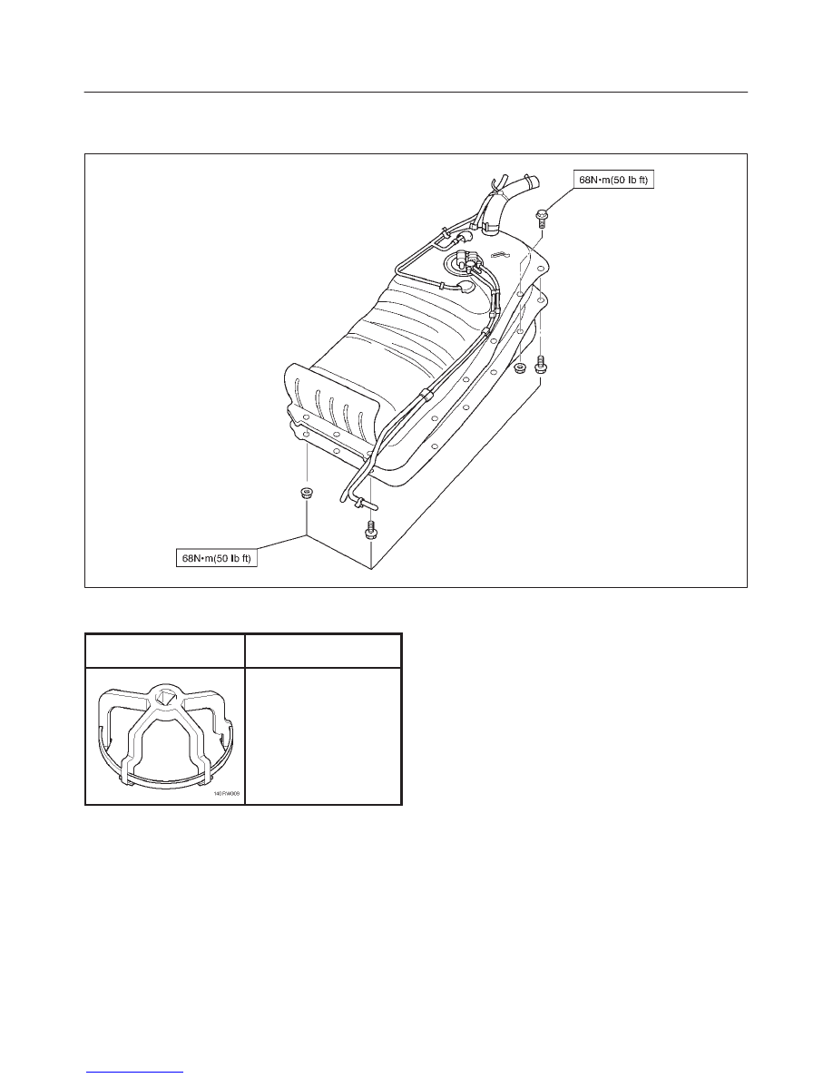
7. Remove the four fuel tank assembly fixing bolts (14)
at four corners of the tank.
8. Let down the tank and disconnect the wiring
connectors (8,9) and the emission hose at the
emission port on the fuel pump and sending assembly
(10).
9. Remove fuel tank assembly along with protectors
(15,19) .
10. Remove retaining cover (2) and roll over&float valve
(1) along with the evaporative fuel hose and pipe (3).
11. Remove Fuel Tube/Quick Connector (12).
NOTE: Handling of fuel tube sure to refer “Fuel
Tube/Quick Connector Fittings” in this section.
12. Remove fuel pump and sender assembly (10) by
removing the snap ring (7) along with the fuel hoses
(17,18).
13. Remove protectors (15,19) by removing the six fixing
bolts (6).
Installation
1. Install protectors (15,19) and tighten the six fixing
bolts to the specified torque.
Torque: 68 N·m (50 lb ft)
2. Install fuel pump and sender assembly by fitting in the
snap ring (7).
3. Install Fuel Tube/Quick Connector (12).
NOTE: Handling of fuel tube sure to refer “Fuel
Tube/Quick Connector Fittings” in this section.
4. Install roll over&float valve (1) by fitting in the retaining
cover (2).
5. Lift up fuel tank assembly and connect the emission
hose to the emission port and the wiring connectors
(8,9) on the fuel pump and sending assembly (10).
6. Install fuel tank assembly along with protectors and
tighten the four fixing bolts to the specified torque.
Torque: 68 N·m (50 lb ft)
7. Connect fuel filler hose (5) and air breather hose (4),
and clip them firmly.
8. Connect fuel feed hose (17) and fuel return hose (18),
and clip them firmly.
9. Connect evaporative fuel hose (3).
10. Tighten fuel filler cap.
11. Connect battery ground cable.
Fuel Gage Unit
Removal and Installation
As for removal and installation of the Fuel Gauge Unit,
refer to “Fuel Tank” of this section 6C as the fuel gauge
unit is combined with the fuel pump and sender assembly.
6C–12
ENGINE FUEL (X22SE 2.2L)
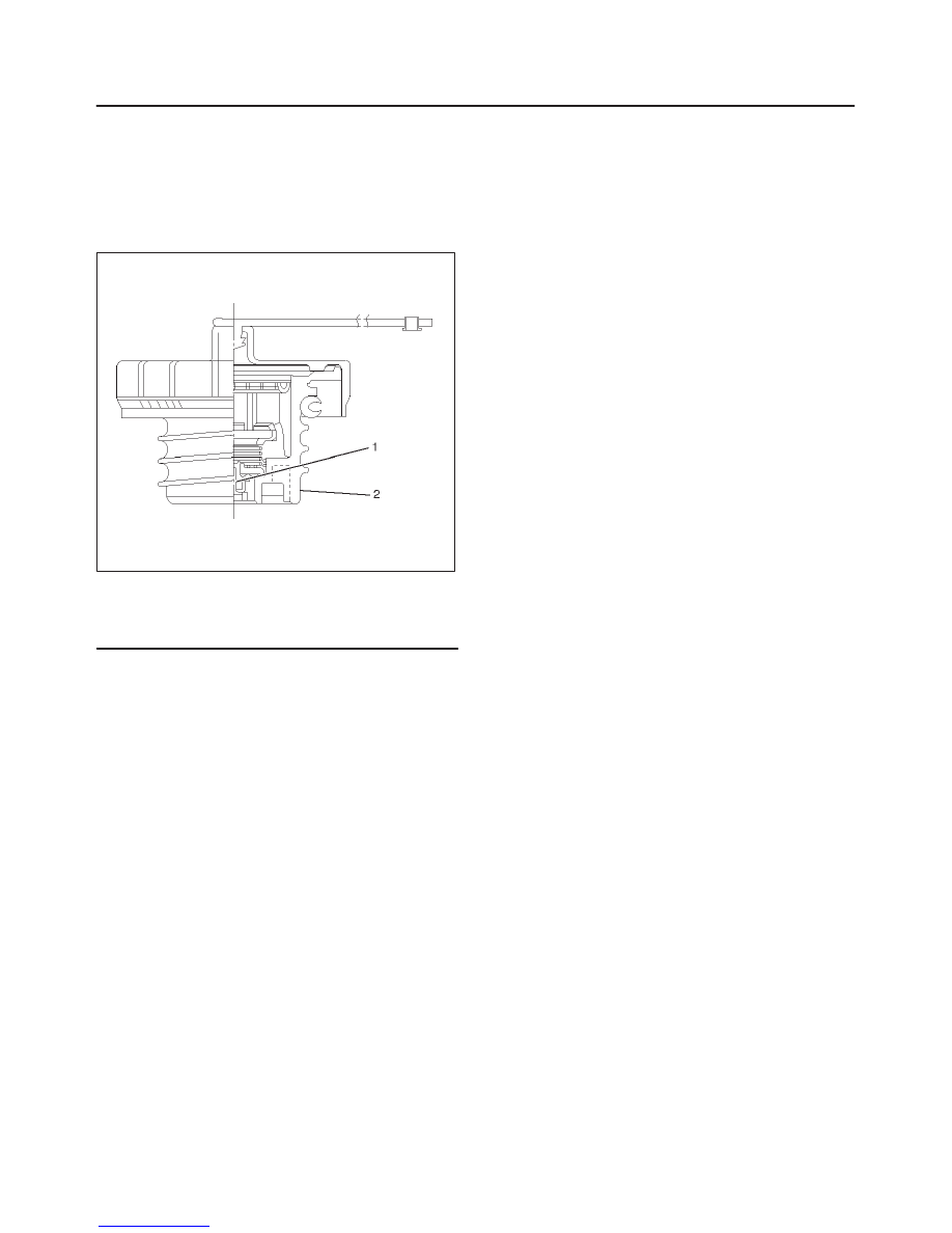
Fuel Filler Cap
General Description
Fuel filler cap includes vacuum valve.
In case any high vacuum happen in tank, the valve works
to adjust the pressure to prevent the tank from being
damaged.
140RW014
Legend
(1) Vacuum Valve
(2) Fuel Filler Cap
Inspection
Check the seal ring in the filler cap for presence of any
abnormality and for seal condition.
Replace the filler cap, if abnormal.
CAUTION:
The fuel filler cap valve has characteristics.
A defective valve, no valve at all or a valve with the
wrong characteristics will do a lot of harm to engine
operating characteristics; be sure to use the same
fuel filler cap as installed in this vehicle.
6C–13
ENGINE FUEL (X22SE 2.2L)
Main Data and Specifications
Torque Specification
140RX009
Special Tool
ILLUSTRATION
TOOL NO.
TOOL NAME
J–39763
Remover; fuel pump
lock
(For S/W)
6D1–1
ENGINE ELECTRICAL (X22SE 2.2L)
RODEO
ENGINE
ENGINE ELECTRICAL (X22SE 2.2L)
CONTENTS
Service Precaution
6D1–1
. . . . . . . . . . . . . . . . . . . . . .
Battery
6D1–2
. . . . . . . . . . . . . . . . . . . . . . . . . . . . . . . . .
General Description
6D1–2
. . . . . . . . . . . . . . . . . . . .
Diagnosis
6D1–2
. . . . . . . . . . . . . . . . . . . . . . . . . . . . .
Battery Charging
6D1–3
. . . . . . . . . . . . . . . . . . . . . .
Jump Starting
6D1–3
. . . . . . . . . . . . . . . . . . . . . . . . .
Battery Removal
6D1–4
. . . . . . . . . . . . . . . . . . . . . .
Battery Installation
6D1–4
. . . . . . . . . . . . . . . . . . . . .
Main Data and Specifications
6D1–5
. . . . . . . . . . .
Service Precaution
WARNING: THIS VEHICLE HAS A SUPPLEMENTAL
RESTRAINT SYSTEM (SRS). REFER TO THE SRS
COMPONENT AND WIRING LOCATION VIEW IN
ORDER TO DETERMINE WHETHER YOU ARE
PERFORMING SERVICE ON OR NEAR THE SRS
COMPONENTS OR THE SRS WIRING. WHEN YOU
ARE PERFORMING SERVICE ON OR NEAR THE SRS
COMPONENTS OR THE SRS WIRING, REFER TO
THE SRS SERVICE INFORMATION. FAILURE TO
FOLLOW WARNINGS COULD RESULT IN POSSIBLE
AIR BAG DEPLOYMENT, PERSONAL INJURY, OR
OTHERWISE UNNEEDED SRS SYSTEM REPAIRS.
CAUTION: Always use the correct fastener in the
proper location. When you replace a fastener, use
ONLY the exact part number for that application.
ISUZU will call out those fasteners that require a
replacement after removal. ISUZU will also call out
the fasteners that require thread lockers or thread
sealant. UNLESS OTHERWISE SPECIFIED, do not
use supplemental coatings (Paints, greases, or other
corrosion inhibitors) on threaded fasteners or
fastener joint interfaces. Generally, such coatings
adversely affect the fastener torque and the joint
clamping force, and may damage the fastener. When
you install fasteners, use the correct tightening
sequence and specifications. Following these
instructions can help you avoid damage to parts and
systems.
Нет комментариевНе стесняйтесь поделиться с нами вашим ценным мнением.
Текст