Isuzu Rodeo UE. Manual — part 558
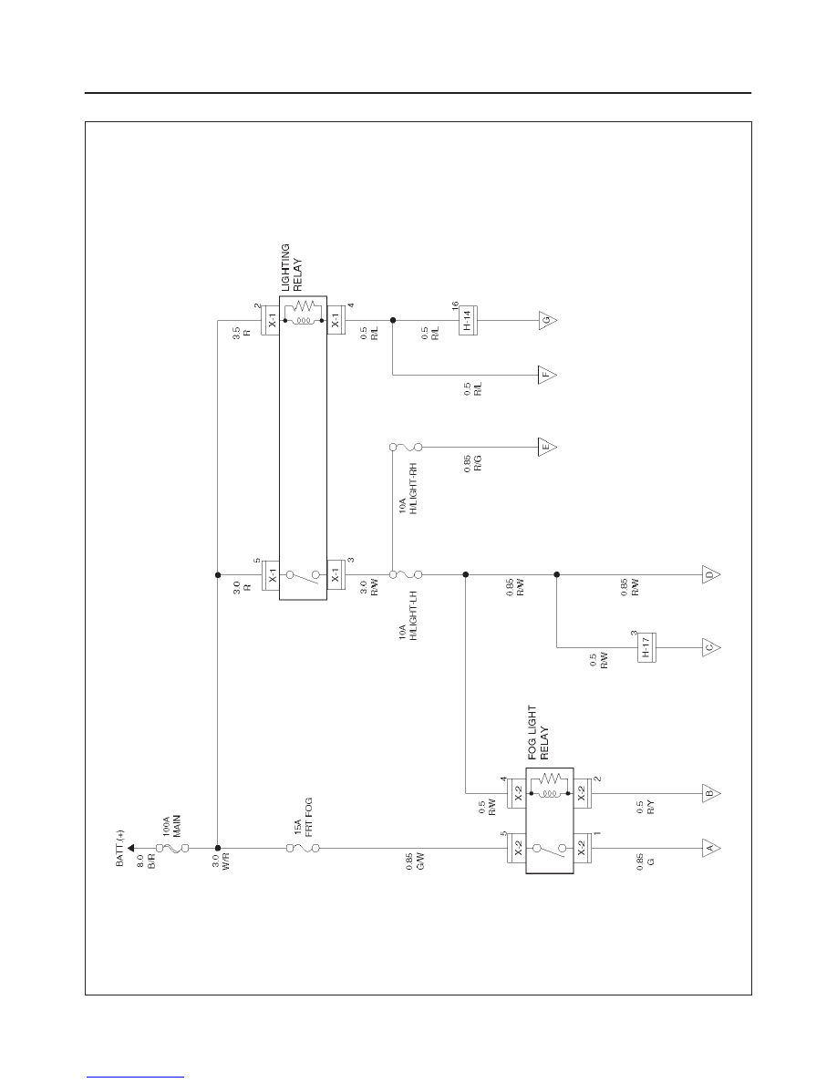
8D–80
WIRING SYSTEM
Circuit Diagram–1
D08RW007
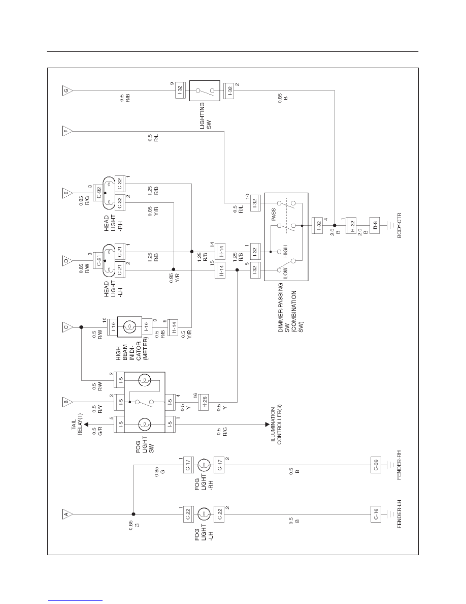
8D–81
WIRING SYSTEM
Circuit Diagram–2
D08RW008
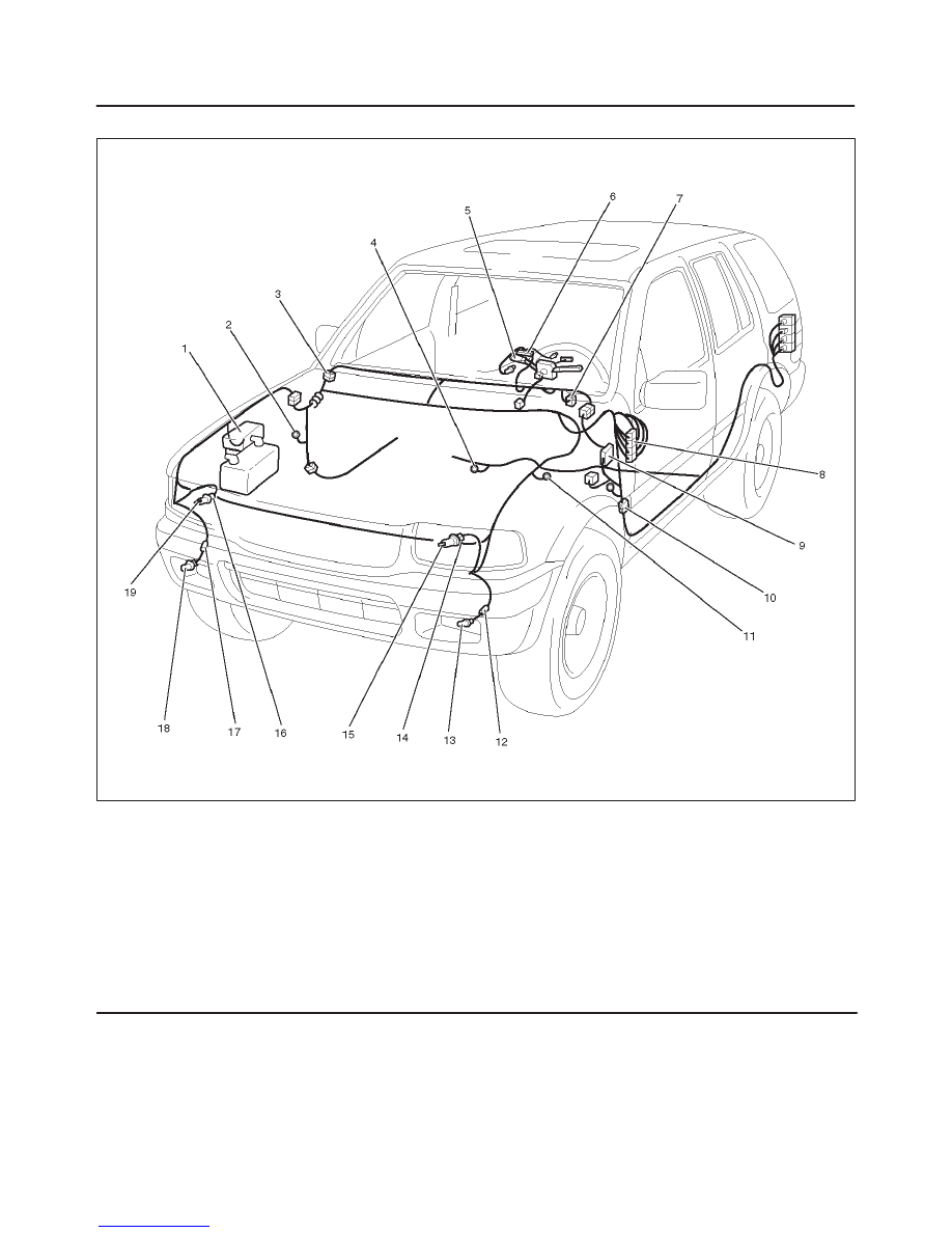
8D–82
WIRING SYSTEM
Parts Location
D08RW107
Legend
(1) X–1, X–2
(2) C–36
(3) H–14
(4) B–8
(5) Lighting SW
(6) I–10
(7) I–5
(8) H–17
(9) I–32 (Combination SW)
(10) H–32
(11) C–16
(12) C–22
(13) Fog Light – LH
(14) C–21
(15) Head Light – LH
(16) C–32
(17) C–17
(18) Fog Light – RH
(19) Head Light – RH
8D–83
WIRING SYSTEM
Diagnosis
Both Headlights Inoperative
Step
Action
Value(s)
Yes
No
1
Check the ground terminal B-8.
B-8 grounded securely?
—
Go to Step 2
Ground it
securely
2
Disconnect the combination switch connector I-32.
Is there continuity between SW connector terminals?
—
Go to Step 3
Repair or
replace the
combination
sw
3
Is there continuity between lighting relay connector
terminals?
—
Go to Step 4
Reinstall or
replace the
lighting relay
4
Check voltage between connector X-1 terminals 5 and
2 ground.
Is there open circuit between battery positive terminal
and lighting relay?
—
Go to Step 5
Repair open
circuit
5
Check voltage between connector I-32 terminal 10
ground.
Is there open circuit between lighting relay and lighting
sw?
—
Go to Step 6
Repair open
circuit or
connector
contact
6
Check continuity between connector I-32 terminal 2
and 4 ground.
Is there open circuit?
—
Repair open
circuit or
connector
contact
—
Headlight On The Left (or Right) Side Inoperative
Step
Action
Value(s)
Yes
No
1
Is the fuse (10A) (or 15A) normal?
—
Go to Step 2
Replace the
fuse
2
Is the headlight bulb on the left (or right) side normal?
—
Go to Step 3
Replace the
bulb
3
Repair a poor connection at the connectors or an open
circuit between fuse (10A) and C-21 terminal 3 (or fuse
(10A) and C-22 terminal 3)
Is the action complete?
—
Verify repair
—
Headlights In Low–Beam Inoperative
Step
Action
Value(s)
Yes
No
1
1. Remove the connector dimmer·passing sw
(combination sw).
2. Set the switch at the low–beam position.
Is there continuity between the sw connector I-32
terminals 5 and 15?
—
Go to Step 2
Repair or
replace the
dimmer·passi
ng sw
2
Repair poor connection at the connectors or an open
circuit between I-32 terminal 5 and H-14 terminal 15.
Is the action complete?
—
Verify repair
—
Нет комментариевНе стесняйтесь поделиться с нами вашим ценным мнением.
Текст