Isuzu Rodeo UE. Manual — part 67
DIFFERENTIAL (REAR)
4A2–33
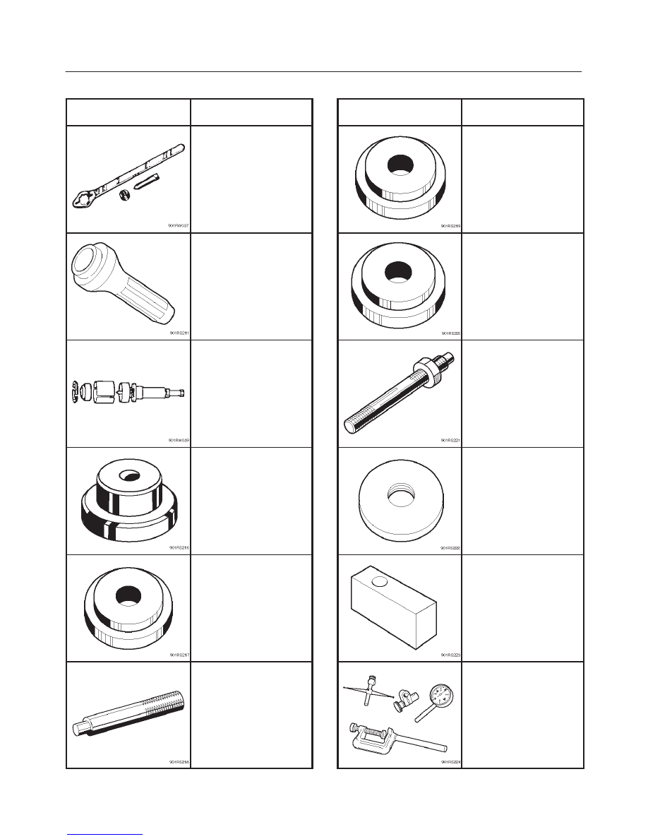
Special Tools
ILLUSTRATION
TOOL NO.
TOOL NAME
J–8614–01
Pinion flange holder
J–37263
Installer; Pinion oil seal
J–42379
Remover; Bearing
J–39830
Adapter; Side bearing
plug
J–8611–01
Installer; Outer bearing
outer race
J–8592
Grip
ILLUSTRATION
TOOL NO.
TOOL NAME
J–42836
Installer; Inner bearing
outer race
J–42824
Pilot;Outer
J–21777–43
Nut & Stud
J–42827
Pilot;Inner
J–39837–2
Gauge plate
J–8001
Dial indicator
4A2–34
DIFFERNTIAL (REAR)
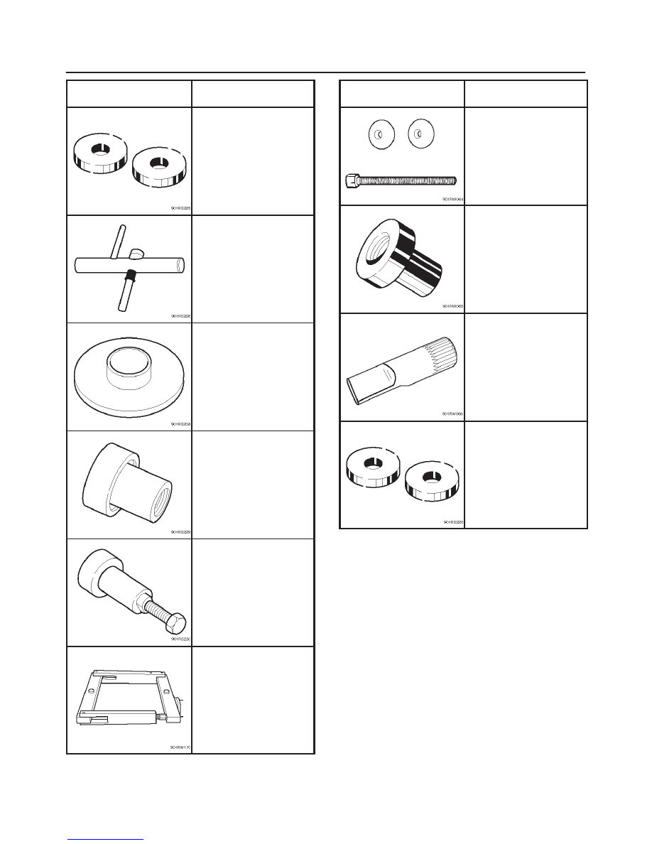
ILLUSTRATION
TOOL NO.
TOOL NAME
J–39837–1
Disc (2 required)
J–23597–1
Arbor
J–42828
Installer; Pinion bearing
J–21784
Installer; Side bearing
J–39602
Remover; Outer bearing
J–24385–B
Spreader
ILLUSTRATION
TOOL NO.
TOOL NAME
J–39858
Clutch pack unloading
tool kit Includes
J–34174–1/J–34174–2
Screw cap and Cap
J–22342–15
Forcing screw
J–39834
Limited–slip differential
(LSD) service adapter
J–39824
Holder
J–39836
Side bearing preload
master bearings
4B–1
DRIVELINE CONTROL SYSTEM
RODEO
DRIVELINE/AXLE
DRIVELINE CONTROL SYSTEM
CONTENTS
Service Precaution
4B–1
. . . . . . . . . . . . . . . . . . . . . .
Shift On The Fly System
4B–2
. . . . . . . . . . . . . . . . .
Outline of Shift on The Fly System
4B–2
. . . . . . . . .
System Diagrams
4B–2
. . . . . . . . . . . . . . . . . . . . .
Normal Operation
4B–3
. . . . . . . . . . . . . . . . . . . . .
Retrial
4B–4
. . . . . . . . . . . . . . . . . . . . . . . . . . . . . . . .
Functions of Indicator Lamp
4B–6
. . . . . . . . . . . . . .
Diagnosis
4B–7
. . . . . . . . . . . . . . . . . . . . . . . . . . . . . .
Before Judging That Troubles Occur
(Unfaulty mode)
4B–7
. . . . . . . . . . . . . . . . . . . . . .
Parts Location
4B–8
. . . . . . . . . . . . . . . . . . . . . . . .
Wiring Diagram
4B–9
. . . . . . . . . . . . . . . . . . . . . . .
Connector List
4B–11
. . . . . . . . . . . . . . . . . . . . . . . .
Diagnosis of The Faults Based on
the Status of 4WD Indicator Lamp,
4WD Switch and T/F Change Lever
4B–12
. . . . .
Shift On The Fly Vacuum Piping and
Electrical Equipment
4B–17
. . . . . . . . . . . . . . . . . . . .
Vacuum Piping Diagram
4B–17
. . . . . . . . . . . . . . . . . .
Inspection and Repair
4B–18
. . . . . . . . . . . . . . . . . . . .
Vacuum Piping
4B–18
. . . . . . . . . . . . . . . . . . . . . . . .
Check Valve
4B–18
. . . . . . . . . . . . . . . . . . . . . . . . . .
VSV Assembly
4B–19
. . . . . . . . . . . . . . . . . . . . . . . .
Functional Detective Switch
4B–19
. . . . . . . . . . . . .
Motor Actuator Assembly
4B–19
. . . . . . . . . . . . . . .
Transfer Position Switch
4B–20
. . . . . . . . . . . . . . . .
4WD Control Unit
4B–21
. . . . . . . . . . . . . . . . . . . . . . .
4WD Control Unit Associated Parts
4B–21
. . . . . .
Removal
4B–22
. . . . . . . . . . . . . . . . . . . . . . . . . . . . .
Installation
4B–22
. . . . . . . . . . . . . . . . . . . . . . . . . . . .
Service Precaution
WARNING: THIS VEHICLE HAS A SUPPLEMENTAL
RESTRAINT SYSTEM (SRS). REFER TO THE SRS
COMPONENT AND WIRING LOCATION VIEW IN
ORDER TO DETERMINE WHETHER YOU ARE
PERFORMING SERVICE ON OR NEAR THE SRS
COMPONENTS OR THE SRS WIRING. WHEN YOU
ARE PERFORMING SERVICE ON OR NEAR THE SRS
COMPONENTS OR THE SRS WIRING, REFER TO
THE SRS SERVICE INFORMATION. FAILURE TO
FOLLOW WARNINGS COULD RESULT IN POSSIBLE
AIR BAG DEPLOYMENT, PERSONAL INJURY, OR
OTHERWISE UNNEEDED SRS SYSTEM REPAIRS.
CAUTION: Always use the correct fastener in the
proper location. When you replace a fastener, use
ONLY the exact part number for that application.
ISUZU will call out those fasteners that require a
replacement after removal. ISUZU will also call out
the fasteners that require thread lockers or thread
sealant. UNLESS OTHERWISE SPECIFIED, do not
use supplemental coatings (Paints, greases, or other
corrosion inhibitors) on threaded fasteners or
fastener joint interfaces. Generally, such coatings
adversely affect the fastener torque and the joint
clamping force, and may damage the fastener. When
you install fasteners, use the correct tightening
sequence and specifications. Following these
instructions can help you avoid damage to parts and
systems.
4B–2
DRIVELINE CONTROL SYSTEM
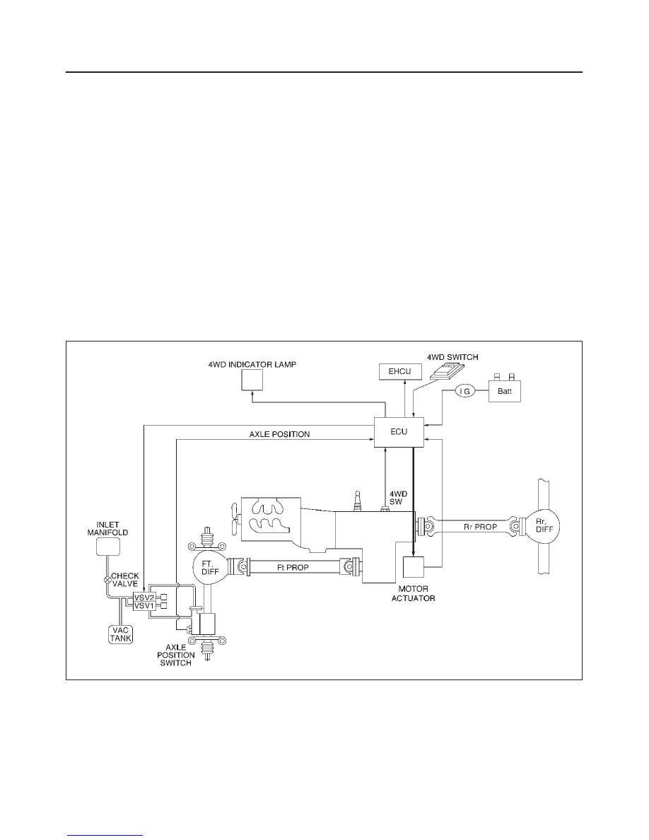
Shift On The Fly System
Outline of Shift on The Fly System
The shift on the fly system switches between 2 wheel
drive (2WD) and 4 wheel drive (4WD) electrically by
driver’s pressing the 4WD switch (push button type) on
instrument panel.
This system controls below operations. (Shifting between
“4H” and “4L” must be performed by transfer control lever
on the floor.)
1. Shifting the transfer front output gear (Connecting to,
and disconnecting from, front propeller shaft by motor
actuator).
2. Retrial of shifting the transfer front output gear.
3. Connecting front wheels to, and disconnecting them
from, the front axles by vacuum actuator.
4. Indicator on instrument panel.
5. 4WD out signal to other Electronic Hydraulic Control
Unit.
System Diagrams
412RX004
Нет комментариевНе стесняйтесь поделиться с нами вашим ценным мнением.
Текст