Isuzu Rodeo UE. Manual — part 211

6E1–215
RODEO X22SE 2.2L ENGINE DRIVEABILITY AND EMISSION
A poor connection at the PCM. Inspect the knock sensor
and the PCM connectors for: , broken locks, improperly
formed or damaged terminals.
f
Backed out terminals
f
Broken locks
f
Improperly formed or damaged terminals
Also, check the wiring harness for: shorts to ground,
shorts to battery positive, and open circuits.
f
A misrouted harness. Inspect the knock sensor
harness in order to ensure that it is not routed too close
to high voltage wires such as spark plug leads.
f
Improper Knock Sensor torque specification. Torque
the Knock Sensor to 19N·m (14 lbs·ft). Refer to
Fastener Notice.
Review the Fail Records vehicle mileage since the
diagnostic test last failed in order to help determine how
often the conditions that caused the DTC to set occur.
This may assist in diagnosing the condition.
Test Description
Number(s) below refer to the step number(s) on the
Diagnostic Chart:
2. Ensures that the fault is present.
6. Ensures that the knock sensor is capable of
detecting detonation.
DTC P0327 KS Circuit Low Input
Step
Action
Value(s)
Yes
No
1
Was the Powertrain ”On–Board Diagnostic (OBD)
System Check” performed?
—
Go to Step 2
Go to
Powertrain
OBD System
Check
2
1. Operate the engine within the conditions specified
in the diagnostic support Conditions for Setting the
DTC.
2. Using a Tech 2, monitor theDiagnostic Trouble
Code information for Diagnostic Trouble Code
P0327 until the Diagnostic Trouble Code P0327 test
runs.
3. Observe the test results.
Does the Tech 2 indicate the DTC P0327 failed this
ignition?
—
Go to Step 4
Go to Step 3
3
1. Turn ON the Ignition leaving the engine OFF.
2. Review the Tech 2 Fail Records data.
3.
IMPORTANT: Before clearing the DTCs, use the Tech
2 to record the Freeze Frame and the Failure Records
for reference. This data will be lost when the Clear Info
function is used.
4. Record the Tech 2 Fail Records data.
5. Operate the vehicle within the Fail Records
conditions.
6. Using a Tech 2, monitor the DTC info for the DTC
P0327 until the DTC P0327 test runs.
7. Observe the test results.
Does the Tech 2 indicate the DTC P0327 Failed This
Ignition?
—
Go to Step 4
Go to
Diagnostic
Aids
4
1. Disconnect the KS Sensor electrical connector.
2. Using a Digital Voltmeter (DVM), measure the
voltage between the KS signal circuit at the knock
sensor harness connectors and ground.
Is the voltage at the specified value?
Approx. 5.0 V
Go to Step 5
Go to Step 8
5
Measure the resistance of the KS sensor by connecting
the between the KS sensor terminal and the engine
block.
Is the resistance of the KS sensor near the specified
value?
100K
W
Go to Step 6
Go to Step 9

6E1–216
RODEO X22SE 2.2L ENGINE DRIVEABILITY AND EMISSION
DTC P0327 KS Circuit Low Input
(Cont'd)
Step
No
Yes
Value(s)
Action
6
1. Check the KS signal circuit for a poor terminal
connection at the knock sensor.
2. If a problem is found, repair as necessary. Refer to
Wiring Repairs in Engine Electrical.
Was a problem found?
—
Go to Step 7
Go to Step 9
7
1. Re–Connect the KS Sensor in order to monitor the
voltage between the KS sensor terminal and the
engine ground.
2. Tap on the engine lift bracket, near the KS Sensor,
while observing the signal indicated on the Tech 2.
Is any signal indicated on the while tapping on the
engine lift bracket?
—
Go to Step
11
Go to Step 8
8
1. Turn OFF the ignition.
2. Disconnect the PCM.
3. Turn ON the ignition.
4. Check the KS signal circuit between the PCM and
the KS sensor connector for an open, a short to
voltage, or a short to ground.
5. If a wiring problem is found, repair as necessary.
Was a problem found?
—
Go to Step
11
Go to Step
10
9
Replace the KS Sensor. Refer to Knock Sensor.
Is the action complete?
—
Go to Step
11
—
10
Replace the PCM.
IMPORTANT: If the PCM is faulty, reprogram the PCM.
Refer to PCM Replacement/Programming.
Is the action complete?
—
Go to Step
11
—
11
1. Using the Tech 2, select the DTC and the Clear Info.
2. Start the engine.
3. Idle at the normal operating temperature.
4. Select the DTC and the Specific.
5. Enter the DTC number which was set.
6. Operate the vehicle within the conditions for setting
this DTC as specified in the supporting text.
Does the Tech 2 indicate that this diagnostic ran and
passed?
—
Go to Step
12
Go to Step 2
12
Using the Tech 2, select the Capture Info and the
Review Info.
Are any DTCs displayed that have not been
diagnosed?
—
Go to
applicable
DTC table
System OK
6E1–217
RODEO X22SE 2.2L ENGINE DRIVEABILITY AND EMISSION
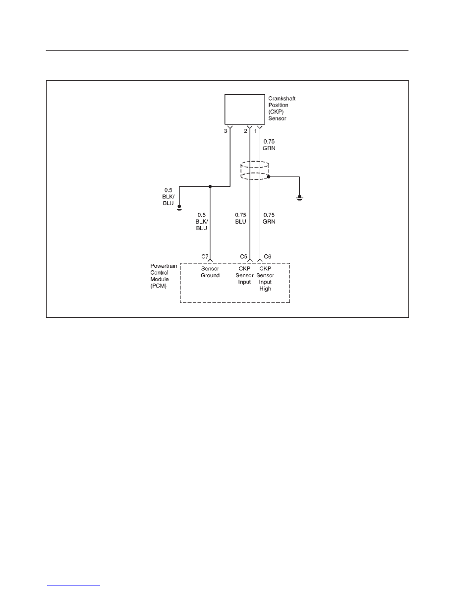
DIAGNOSTIC TROUBLE CODE (DTC) P0336 CRANKSHAFT POSITION (CKP)
SENSOR CIRCUIT RANGE/PERFORMANCE
D06RX052
Circuit Description
The 58X reference signal is produced by the crankshaft
position (CKP) sensor. During one crankshaft revolution,
58 crankshaft pulses will be produced. The powertrain
control module (PCM) uses the 58X reference signal to
calculate engine RPM and crankshaft position. The PCM
constantly monitors the number of pulses on the 58X
reference circuit and compares them to the number of
camshaft position (CMP) signal pulses being received. If
the PCM receives an incorrect number of pulses on the
58X reference circuit, Diagnostic Trouble Code P0336 will
set. Diagnostic Trouble Code P0336 is a type B code.
Conditions for Setting the DTC
f
Engine is running.
f
Extra or missing pulse is detected between
consecutive 58X reference pulses.
f
Above condition is detected in 10 of 100 crankshaft
rotations.
Action Taken When the DTC Sets
f
The PCM will illuminate the malfunction indicator lamp
(MIL) after the second consecutive trip in which the
fault is detected.
f
The PCM will store conditions which were present
when the Diagnostic Trouble Code was set as Freeze
Frame and in the Failure Records data.
Conditions for Clearing the MIL/DTC
f
The PCM will turn the MIL OFF on the third consecutive
trip cycle during which the diagnostic has been run and
the fault condition is no longer present.
f
A history Diagnostic Trouble Code P0336 will clear
after 40 consecutive warm–up cycles have occurred
without a fault.
f
Diagnostic Trouble Code P0336 can be cleared by
using the Scan Tool’s ”Clear Info” function.
Diagnostic Aids
An intermittent may be caused by a poor connection,
rubbed–through wire insulation or a wire broken inside the
insulation. Check for:
f
Poor connection – Inspect the PCM harness and
connectors for improper mating, broken locks,
improperly formed or damaged terminals, and poor
terminal–to–wire connection.
f
Damaged harness – Inspect the wiring harness for
damage; shorts to ground, shorts to battery positive
and open circuits. If the harness appears to be OK,
disconnect the PCM, turn the ignition on and observe
a voltmeter connected to the 58X reference circuit at
the PCM harness connector while moving connectors
and wiring harnesses related to the PCM. A change in
voltage will indicate the location of the fault.
Reviewing the Failure Records vehicle mileage since the
diagnostic test last failed may help determine how often
the condition that caused the Diagnostic Trouble Code to

6E1–218
RODEO X22SE 2.2L ENGINE DRIVEABILITY AND EMISSION
be set occurs. This may assist in diagnosing the
condition.
DTC P0336 – CKP Sensor Circuit Range/Performance
Step
Action
Value(s)
Yes
No
1
Was the ”On–Board Diagnostic (OBD) System Check”
performed?
—
Go to Step 2
Go to OBD
System
Check
2
Attempt to start the engine.
Does the engine start?
—
Go to Step 3
Refer to
Engine
Cranks But
Will Not Run
chart
3
1. Review and record Failure Records information.
2. Clear Diagnostic Trouble Code P0336.
3. Start the engine and idle for 1 minute.
4. Observe Diagnostic Trouble Codes.
Is Diagnostic Trouble Code P0336 set?
—
Go to Step 4
Refer to
Diagnostic
Aids
4
1. Disconnect the PCM and CKP sensor.
2. Check for an open or a short to ground in the 58X
reference circuit between the CKP sensor
connector and the PCM harness connector.
3. If a problem is found, repair as necessary.
Was a problem found?
—
Verify repair
Go to Step 5
5
1. Reconnect the PCM and CKP sensor.
2. Connect a Digital Voltmeter (DVM) to measure
voltage on the 58X reference circuit at the PCM
connector.
3. Observe the voltage while cranking the engine.
Is the voltage near the specified value?
2.5 V
Go to Step 8
Go to Step 6
6
Check the connections at the CKP sensor and replace
the terminals if necessary.
Did any terminals require replacement?
—
Verify repair
Go to Step 7
7
Replace the CKP sensor.
IMPORTANT: The PCM must go through the Scan
Tool’s Tooth Error Correction (TEC) procedure after
CKP Sensor replacement. Refer to the Tooth Error
Correction procedure.
Is the action complete?
—
Verify repair
—
8
Check connections at the PCM and replace the
terminals if necessary.
Did any terminals require replacement?
—
Verify repair
Go to Step 9
9
Replace the PCM.
IMPORTANT: The replacement PCM must be
programmed. Refer to On–Vehicle Service in
Powertrain Control Module and Sensors for
procedures.
And also refer to latest Service Bulletin.
Check to see if the Latest software is released or not.
And then Down Load the LATEST PROGRAMMED
SOFTWARE to the replacement PCM.
Is the action complete?
—
Verify repair
—
Нет комментариевНе стесняйтесь поделиться с нами вашим ценным мнением.
Текст