Isuzu Rodeo UE. Manual — part 439
6E2–511
RODEO 6VD1 3.2L ENGINE DRIVEABILITY AND EMISSIONS
positive crankcase ventilation (PCV) valve into the
common chamber.
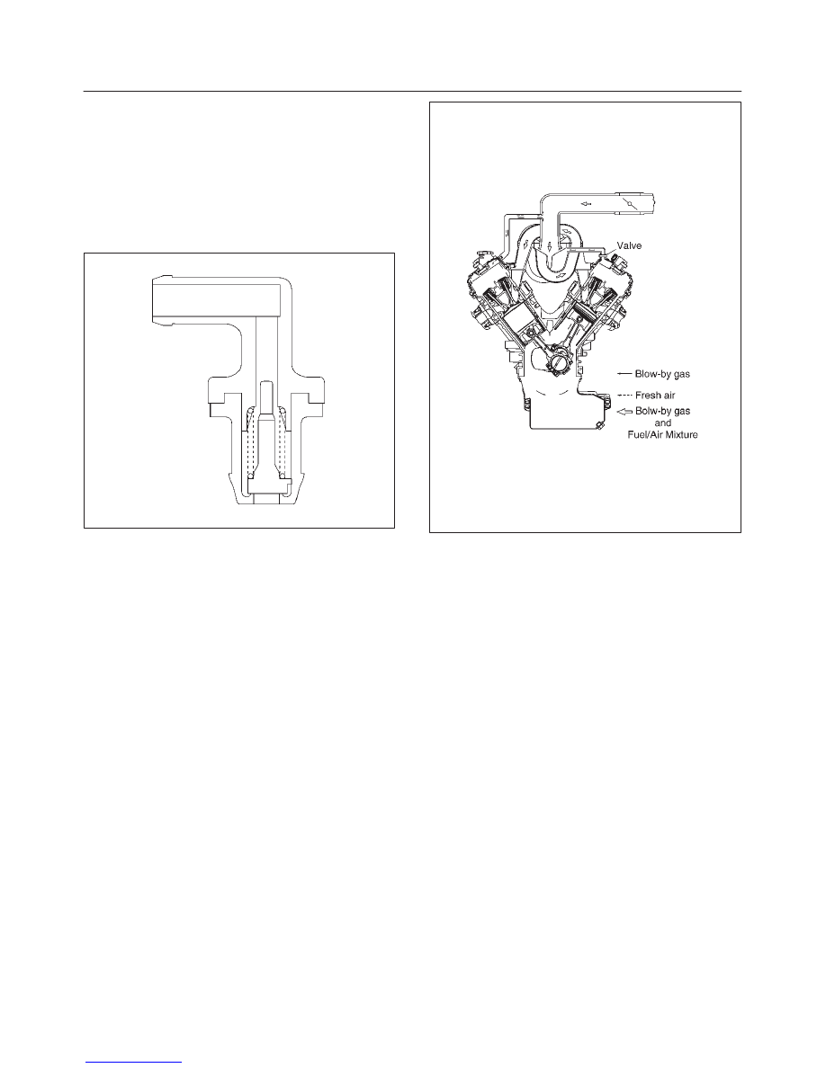
Crankcase Ventilation System Operation
The primary control is through the positive crankcase
ventilation (PCV) valve. The PCV valve meters the flow at
a rate that depends on the intake vacuum. The PCV valve
restricts the flow when the inlet vacuum is highest. In
addition, the PCV valve can seal the common chamber
off in case of sudden high pressure in the crankcase.
028RV002
While the engine is running, exhaust fuses and small
amounts of the fuel/air mixture escape past the piston
rings and enter the crankcase. These gases are mixed
with clean air entering through a tube from the air intake
duct.
028RW002
During normal, part-throttle operation, the system is
designed to allow crankcase gases to flow through the
PCV valve into the throttle body to be consumed by
normal combustion.
A plugged valve or PCV hose may cause the following
conditions:
f
Rough idle.
f
Stalling of slow idle speed.
f
Oil leaks.
f
Sludge in the engine.
A leaking PCV hose would cause:
f
Rough idle.
f
Stalling.
f
High idle speed.
6E2–512
RODEO 6VD1 3.2L ENGINE DRIVEABILITY AND EMISSIONS
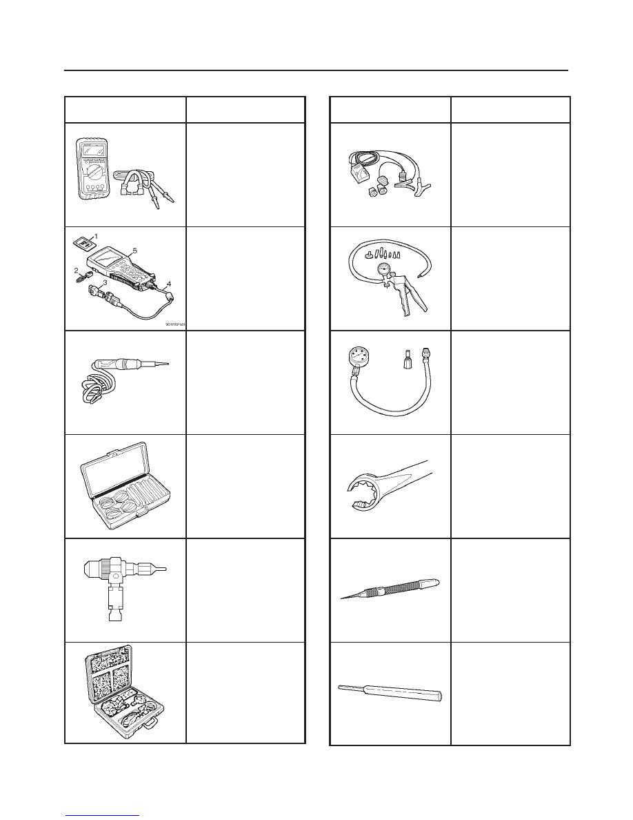
Special Tools
ILLUSTRATION
TOOL NO.
TOOL NAME
J 39200
High Impedance
Multimeter (Digital
Voltmeter – DVM)
(1) PCMCIA Card
(2) RS232 Loop Back
Connector
(3) SAE 16/19 Adapter
(4) DLC Cable
(5) TECH–2
J 34142-B
Unpowered Test Light
Connector Test Adapter
Kit J 35616-A/BT-8637
J 26792/BT-7220-1
Spark Tester
J 34730-E
Port Fuel Injection
Diagnostic Kit
ILLUSTRATION
TOOL NO.
TOOL NAME
J 37027-A
IAC Motor Analyzer
J 23738-A
Vacuum Pump with
Gauge
BT-8515/8515V
Exhaust Back Pressure
Tester
J 39194-B
Heated Oxygen Sensor
Wrench
J 35689-A
Terminal Remover
J 28742-A
Weather Pack II
Terminal Remover
6E2–513
RODEO 6VD1 3.2L ENGINE DRIVEABILITY AND EMISSIONS
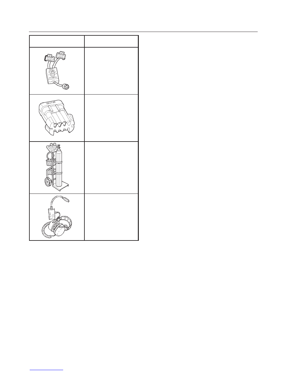
ILLUSTRATION
TOOL NO.
TOOL NAME
J 39021-90
Injector Switch Box
J 39021-65
Injector Test Light
J 41413
!
EVAP Pressure/Purge
Diagnostic Station
J 41416
@
Ultrasonic Leak Detector
1. J 41413 EVAP Pressure/Purge Diagnostic Station is
a multipurpose tool which is used to perform several
diagnostic procedures for enhanced emission
testing. The station will accommodate a nitrogen gas
filled cylinder which is used to pressurize the vehicle
EVAP system for a leakdown test and leak location
test when a vehicle is repaired for leakage in the
enhanced evaporative emission control system. It
also has two additional gauges (inches of mercury
and inches of water) which are used to measure both
source vacuum and EVAP canister purge vacuum to
verify correct operation and vapor flow within the
canister purge circuit.
2. J 41416 Ultrasonic Leak Detector is a
microprocessor-based device used to detect leaks in
the enhanced evaporative emission control system.
The evaporative system is pressurized to 30 inches of
water using the J 41413 EVAP Pressure/Purge
Diagnostic System. Small leaks in the EVAP system
will emit sound at a high frequency undetectable by a
human ear but detectable with the J 41416. The
technician traces along the evaporative system and
can pinpoint leaks due to corroded lines, cracked
hoses, or a damaged EVAP component. The
detector includes a high quality set of headphones to
block out surrounding shop noise and the LED
sensitivity meter allows a visual reference for locating
leaks in conjunction with the audio output heard
through the headphones. Powered by (1) nine volt
battery.
6F–1
ENGINE EXHAUST (6VD1 3.2L)
RODEO
ENGINE
ENGINE EXHAUST (6VD1 3.2L)
CONTENTS
Service Precaution
6F–1
. . . . . . . . . . . . . . . . . . . . . .
General Description
6F–2
. . . . . . . . . . . . . . . . . . . . .
Three Way Catalytic Converter RH and
Forked Exhaust Pipe
6F–3
. . . . . . . . . . . . . . . . . . . .
Three Way Catalytic Converter RH and
Forked Exhaust Pipe and Associated Parts
6F–3
Removal
6F–3
. . . . . . . . . . . . . . . . . . . . . . . . . . . . .
Installation
6F–3
. . . . . . . . . . . . . . . . . . . . . . . . . . . .
Three Way Catalytic Converter LH and
Forked Exhaust Pipe
6F–4
. . . . . . . . . . . . . . . . . . . .
Three Way Catalytic Converter LH and
Forked Exhaust Pipe and Associated Parts
6F–4
Removal
6F–4
. . . . . . . . . . . . . . . . . . . . . . . . . . . . .
Installation
6F–4
. . . . . . . . . . . . . . . . . . . . . . . . . . . .
Forked Exhaust Pipe
6F–5
. . . . . . . . . . . . . . . . . . . .
Forked Exhaust Pipe and Associated Parts
6F–5
Removal
6F–5
. . . . . . . . . . . . . . . . . . . . . . . . . . . . .
Installation
6F–5
. . . . . . . . . . . . . . . . . . . . . . . . . . . .
Exhaust Silencer
6F–6
. . . . . . . . . . . . . . . . . . . . . . . .
Exhaust Silencer and Associated Parts
6F–6
. . .
Removal
6F–6
. . . . . . . . . . . . . . . . . . . . . . . . . . . . .
Installation
6F–6
. . . . . . . . . . . . . . . . . . . . . . . . . . . .
Rear Exhaust pipe
6F–7
. . . . . . . . . . . . . . . . . . . . . . .
Rear Exhaust pipe and Associated Parts
6F–7
.
Removal
6F–7
. . . . . . . . . . . . . . . . . . . . . . . . . . . . .
Installation
6F–7
. . . . . . . . . . . . . . . . . . . . . . . . . . . .
Main Data and Specifications
6F–8
. . . . . . . . . . . . .
Service Precaution
WARNING: THIS VEHICLE HAS A SUPPLEMENTAL
RESTRAINT SYSTEM (SRS). REFER TO THE SRS
COMPONENT AND WIRING LOCATION VIEW IN
ORDER TO DETERMINE WHETHER YOU ARE
PERFORMING SERVICE ON OR NEAR THE SRS
COMPONENTS OR THE SRS WIRING. WHEN YOU
ARE PERFORMING SERVICE ON OR NEAR THE SRS
COMPONENTS OR THE SRS WIRING, REFER TO
THE SRS SERVICE INFORMATION. FAILURE TO
FOLLOW WARNINGS COULD RESULT IN POSSIBLE
AIR BAG DEPLOYMENT, PERSONAL INJURY, OR
OTHERWISE UNNEEDED SRS SYSTEM REPAIRS.
CAUTION: Always use the correct fastener in the
proper location. When you replace a fastener, use
ONLY the exact part number for that application.
ISUZU will call out those fasteners that require a
replacement after removal. ISUZU will also call out
the fasteners that require thread lockers or thread
sealant. UNLESS OTHERWISE SPECIFIED, do not
use supplemental coatings (Paints, greases, or other
corrosion inhibitors) on threaded fasteners or
fastener joint interfaces. Generally, such coatings
adversely affect the fastener torque and the joint
clamping force, and may damage the fastener. When
you install fasteners, use the correct tightening
sequence and specifications. Following these
instructions can help you avoid damage to parts and
systems.
Нет комментариевНе стесняйтесь поделиться с нами вашим ценным мнением.
Текст