Isuzu Rodeo UE. Manual — part 179
6E1–87
RODEO X22SE 2.2L ENGINE DRIVEABILITY AND EMISSION
FUEL SYSTEM ELECTRICAL TEST
D06RX040
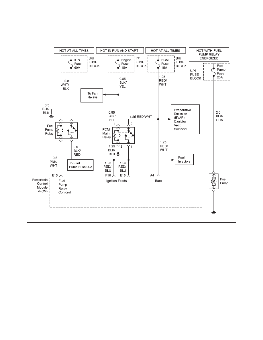
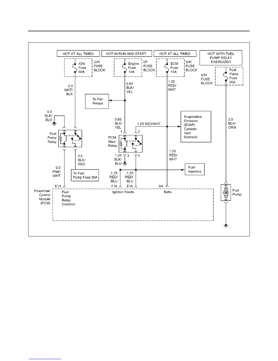
Circuit Description
When the ignition switch is first turned ON, the powertrain
control module (PCM) energizes the fuel pump relay
which applies power to the in–tank fuel pump. The fuel
pump relay will remain ON as long as the engine is
running or cranking and the PCM is receiving 58X
crankshaft position pulses. If no 58X crankshaft position
pulses are present, the PCM de–energizes the fuel pump
relay within 2 seconds after the ignition is turned ON or the
engine is stopped.
The fuel pump delivers fuel to the fuel rail and injectors,
then to the fuel pressure regulator. The fuel pressure
regulator controls fuel pressure by allowing excess fuel to
be returned to the fuel tank. With the engine stopped and
ignition ON, the fuel pump can be turned ON by using a
command by the Tech 2.
Diagnostic Aids
An intermittent may be caused by a poor connection,
rubbed–through wire insulation, or a wire broken inside
the insulation. Check for the following items:
f
Poor connection or damaged harness – Inspect the
PCM harness and connectors for improper mating,
broken locks, improperly formed or damaged
terminals, poor terminal–to–wire connection, and
damaged harness.
Test Description
Number(s) below refer to the step number(s) on the
Diagnostic Chart:
2. If the fuel pump is operating but incorrect pressure
is noted, the fuel pump wiring is OK and the ”Fuel
System Pressure Test” chart should be used for
diagnosis.
6E1–88
RODEO X22SE 2.2L ENGINE DRIVEABILITY AND EMISSION
CAUTION: To reduce the risk of fire and personal
injury:
f
It is necessary to relieve fuel system pressure
before connecting a fuel pressure gauge. Refer to
Fuel Pressure Relief Procedure, below.
f
A small amount of fuel may be released when
disconnecting the fuel lines. Cover fuel line
fittings with a shop towel before disconnecting, to
catch any fuel that may leak out. Place the towel in
an approved container when the procedure is
completed.
Fuel Pressure Relief Procedure
1. Remove the fuel cap.
2. Remove the fuel pump relay from the underhood
relay center.
3. Start the engine and allow it to stall.
4. Crank the engine for an additional 3 seconds.
Fuel Gauge Installation
1. Remove the shoulder fitting cap.
2. Install fuel gauge J 34730–1 to the fuel feed line
located in front of and above the right side valve
cover.
3. Reinstall the fuel pump relay.
Fuel System Electrical Test
Step
Action
Value(s)
Yes
No
1
Was the ”On–Board Diagnostic (OBD) System Check”
performed?
—
Go to Step 2
Go to OBD
System
Check
2
1. Read the ”Caution” above.
2. Relieve the fuel system pressure and install the fuel
pump pressure gauge to the test fitting.
3. Use a Tech 2 to command the fuel pump ON.
Is there an immediate pressure build–up which
indicates the pump is running?
—
Go to Step 3
Go to Step 4
3
1. Verify that the pump is not running by removing the
fuel filler cap and listening.
2. Command the pump ON with the Tech 2.
Did the pump turn OFF after 2 seconds?
—
Test
completed
Go to Step 12
4
1. Ignition OFF.
2. Remove the fuel pump relay.
3. Ignition SW “On”, Engin Off.
4. Using a test light connected to ground, probe the
battery feed to the relay.
Did the light illuminate?
—
Go to Step 6
Go to Step 5
5
Repair short or open battery feed to fuel pump relay.
Is the action complete?
—
Verify repair
—
6
1. Connect a test light between the two wires that
connect to the fuel pump relay pull–in coil.
2. Ignition ON.
Did the test light illuminate for 2 seconds and then turn
off?
—
Go to Step 12
Go to Step 7
7
1. With a test light connected to battery (–), probe the
fuel pump relay connector at the wire which runs
from the relay pull–in coil to the PCM.
2. Ignition ON.
Did the test light illuminate for 2 seconds and then turn
off?
—
Go to Step 8
Go to Step 9
8
Locate and repair open in the fuel pump relay ground
circuit.
Is the action complete?
—
Verify repair
—
6E1–89
RODEO X22SE 2.2L ENGINE DRIVEABILITY AND EMISSION
Fuel System Electrical Test
(Cont'd)
Step
No
Yes
Value(s)
Action
9
Check for short or open between the PCM and the fuel
pump relay.
Was a problem found?
—
Verify repair
Go to Step 10
10
1. Check the fuel pump relay circuit for a poor terminal
connection at the PCM.
2. If a problem is found, replace terminal as necessary.
Was a problem found?
—
Verify repair
Go to Step 11
11
Replace the PCM.
IMPORTANT: The replacement PCM must be
programmed. Refer to On–Vehicle Service in
Powertrain Control Module and Sensors for
procedures.
and also refer to latest service bulletin.
Check to see if the Latest software is released or not.
And then Down Load the LATEST PROGRAMMED
SOFTWARE to the replacement PCM.
Is the action complete?
—
Verify repair
—
12
1. Reconnect the fuel pump relay.
2. Disconnect the fuel pump electrical connector at the
fuel tank.
3. Using a test light connected to ground, probe the
fuel pump feed wire (harness side).
4. Command the fuel pump ON with a Tech 2.
Did the light illuminate for 2 seconds?
—
Go to Step 15
Go to Step 13
13
1. Honk the horn to verify that the horn relay is
functioning.
2. Substitute the horn relay for the fuel pump relay.
3. Leave the test light connected as in step 12.
4. Command the fuel pump ON with the Tech 2.
Did the test light illuminate for 2 seconds when the fuel
pump was commanded ON?
—
Go to Step 17
Go to Step 14
14
1. Re–connect the horn relay in its proper location.
2. Check for a short circuit, blown fuse or open circuit
between the relay and the fuel tank.
Is the action complete?
—
Verify repair
—
15
1. With the fuel pump electrical connector at the fuel
tank disconnected, connect a test light between the
feed wire and the ground wire (harness side).
2. Command the fuel pump ON with a Tech 2.
Did the test light illuminate for 2 seconds?
—
Go to Step 18
Go to Step 16
16
Repair the open circuit in the fuel pump ground wire.
Is the action complete?
—
Verify repair
—
17
1. Re–connect the horn relay in its proper location.
2. Replace the fuel pump relay.
Is the action complete?
—
Verify repair
—
18
Replace the fuel pump.
Is the action complete?
—
Verify repair
—
6E1–90
RODEO X22SE 2.2L ENGINE DRIVEABILITY AND EMISSION
FUEL SYSTEM DIAGNOSIS
D06RX040
Circuit Description
When the ignition switch is turned ON, the powertrain
control module (PCM) will turn ON the in–tank fuel pump.
The in–tank fuel pump will remain ON as long as the
engine is cranking or running and the PCM is receiving
58X crankshaft position pulses. If there are no 58X
crankshaft position pulses, the PCM will turn the in–tank
fuel pump OFF 2 seconds after the ignition switch is
turned ON or 2 seconds after the engine stops running.
The in–tank fuel pump is an electric pump within an
integral reservoir. The in–tank fuel pump supplies fuel
through an in–line fuel filter to the fuel rail assembly. The
fuel pump is designed to provide fuel at a pressure above
the pressure needed by the fuel injectors. A fuel pressure
regulator, attached to the fuel rail, keeps the fuel available
to the fuel injectors at a regulated pressure. Unused fuel is
returned to the fuel tank by a separate fuel return line.
Test Description
Number(s) below refer to the step number(s) on the
Diagnostic Chart:
2. Connect the fuel pressure gauge to the fuel feed
line as shown in the fuel system illustration. Wrap a
shop towel around the fuel pressure connection in
order to absorb any fuel leakage that may occur
when installing the fuel pressure gauge. With the
ignition switch ON and the fuel pump running, the
fuel pressure indicated by the fuel pressure gauge
should be 283–376 kPa (41–55 psi). This pressure
is controlled by the amount of pressure the spring
inside the fuel pressure regulator can provide.
3. A fuel system that cannot maintain a constant fuel
pressure has a leak in one or more of the following
areas:
f
The fuel pump check valve.
f
The fuel pump flex line.
Нет комментариевНе стесняйтесь поделиться с нами вашим ценным мнением.
Текст