Isuzu Rodeo UE. Manual — part 162
6E1–19
RODEO X22SE 2.2L ENGINE DRIVEABILITY AND EMISSION
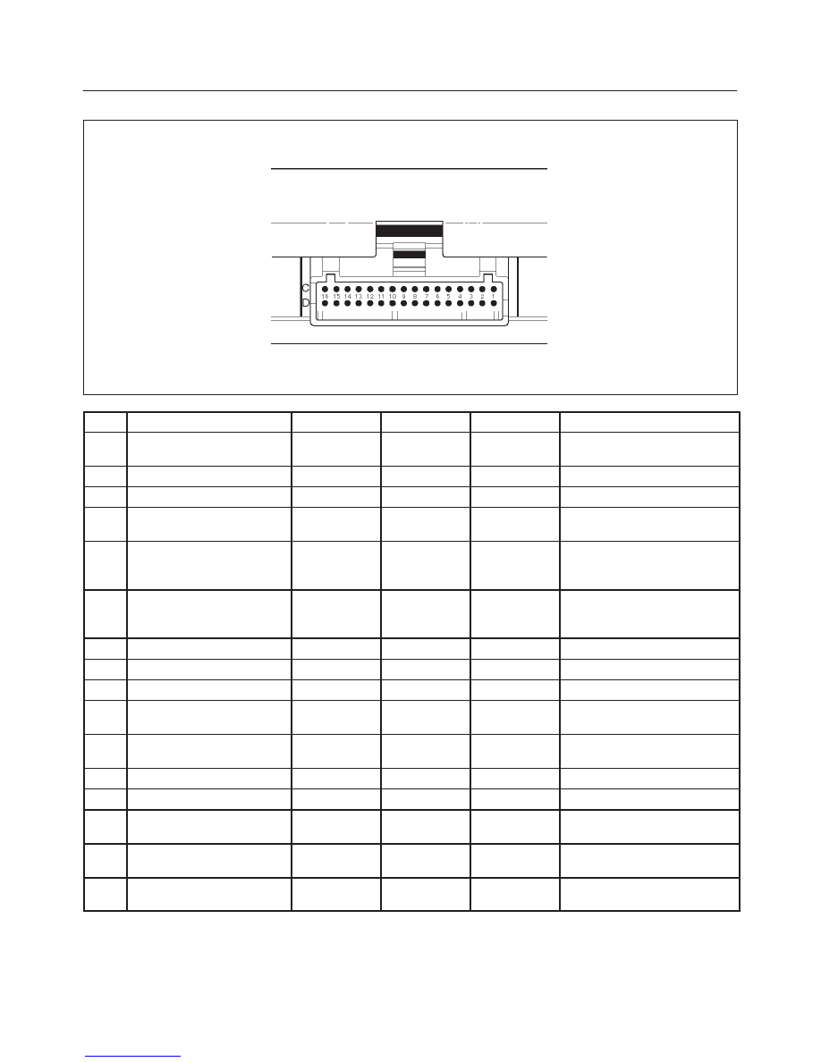
PCM Pinout Table, 32–Pin White Connector – Row ”C”
TS23345
PIN
PIN Function
Wire Color
IGN ON
ENG RUN
Refer To
C1
Injector Cylinder #2
GRN/RED
B+ Varies
B+ Varies
General Description and
Operation, Fuel Injector
C2
Not Used
—
—
—
—
C3
Not Used
—
—
—
—
C4
Ignition Control Module
(ICM) Input
RED
0.0 V
0.1 V
General Description and
Operation, Fuel Injector
C5
Crankshaft Position (CKP)
Sensor Low
BLUE
4.98 V
0.76 V (at
idle)
General Description and
Operation, Crankshaft
Position Sensor
C6
Crankshaft Position
Sensor (CKP) High
GRN
5V
5V
General Description and
Operation, Crankshaft
Position Sensor
C7
PCM Ground
BLK/BLU
0.0 V
0.0 V
Chassis Electrical
C8
PCM Ground
BLK/BLU
0.0 V
0.0 V
Chassis Electrical
C9
PCM Ground
BLK/BLU
0.0 V
0.0 V
Chassis Electrical
C10
Tachometer Signal
BLK/RED
—
—
General Description and
Operation
C11
Fuel Gauge PWM Output
YEL/RED
Varies with
Fuel Level
Varies with
Fuel Level
General Description and
Operation
C12
High Fan Relay Control
RED/YEL
10.5 V
B+
Chassis Electrical
C13
Low Fan Relay Control
RED/BLU
—
—
Chassis Electrical
C14
Bank 1 HO2S 1 High
WHT
0.3 V
–0.1 to 1.1 V
General Description and
Operation, Fuel HO2S 1
C15
Bank 1 HO2S 1 Low
RED
0.0 V
0.1 V
General Description and
Operation, Fuel HO2S 1
C16
Bank 1 HO2S 2 High
RED
0.3 V
–0.1 to 1.1 V
General Description and
Operation, Catalyst HO2S 2
6E1–20
RODEO X22SE 2.2L ENGINE DRIVEABILITY AND EMISSION
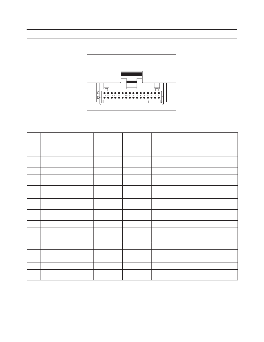
PCM Pinout Table, 32–Pin White Connector – Row ”D”
TS23345
PIN
PIN Function
Wire Color
IGN ON
ENG RUN
Refer To
D1
Injector Cylinder #3
GRN/ORN
B+
B+
General Description and
Operation, Fuel Injector
D2
Not Used
—
—
—
—
D3
Injector Cylinder #1
GRN/WHT
B+
B+
General Description and
Operation, Fuel Injector
D4
Not Used
—
—
—
—
D5
Ignition Control Module
(ICM) Input
RED/BLK
—
—
General Description and
Operation
D6
Not Used
—
—
—
—
D7
VSS Input
BLU/BLK
—
—
Chassis Electrical
D8
Sensor Ground 5 V
Reference A Return
GRN
0.0 V
0.0 V
Appropriate Sensor
D9
Sensor Ground 5 V
Reference B Return
BLU/YEL
0.0 V
0.0 V
Appropriate Sensor
D10
Not Used
—
—
—
—
D11
Camshaft Position Sensor
Input
BLU
5.0 V
4.6 V
General Description and
Operation, Camshaft
Position Sensor
D12
Not Used
—
—
—
—
D13
Not Used
—
—
—
—
D14
Not Used
—
—
—
—
D15
Not Used
—
—
—
—
D16
Bank 1 HO2S 2 Low
GRN
0.0 V
0.1 V
General Description and
Operation, Catalyst HO2S 2
6E1–21
RODEO X22SE 2.2L ENGINE DRIVEABILITY AND EMISSION
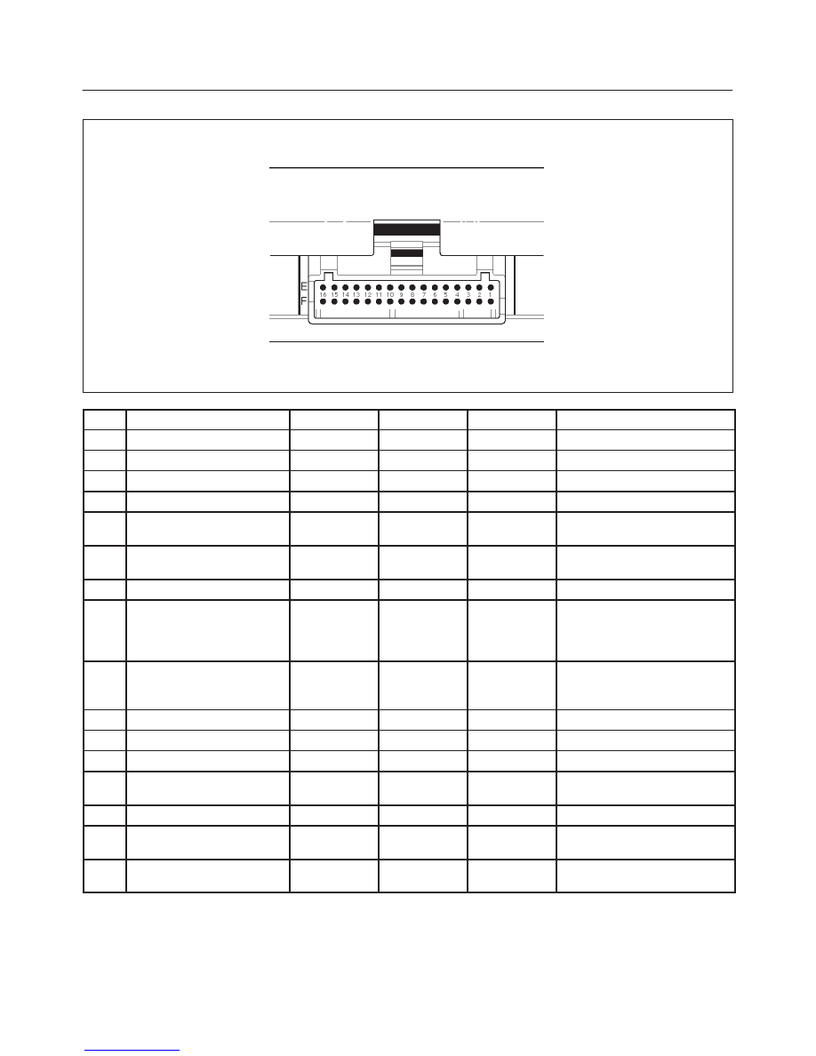
PCM Pinout Table, 32–Pin White Connector – Row ”E”
TS23346
PIN
PIN Function
Wire Color
IGN ON
ENG RUN
Refer To
E1
Not Used
—
—
—
—
E2
Fan Control
RED/GRN
0.0V
B+
Chassis Electrical
E3
Not Used
—
—
—
—
E4
Not Used
—
—
—
—
E5
Ignition Feed
BLK/YEL
B+
B+
General Description and
Operation
E6
Exhaust Gas Recirculation
(EGR) Valve Low
YEL
B+ Varies
B+ Varies
General Description and
Operation, EGR Control
E7
Not Used
—
—
—
—
E8
Throttle Position (TP)
Sensor Input
BLU
0.25 V
(0% = 0.25 V)
0.25 V
(at idle)
(100% = 4.75
V)
General Description and
Operation, Throttle Position
Sensor
E9
Engine Coolant
Temperature (ECT)
Sensor Input
BLU/RED
2.3 V
(O V =
151
°
C)
2.1 V
(5 V = –40
°
C)
General Description and
Operation, Engine Coolant
Temperature (ECT) Sensor
E10
Not Used
—
—
—
—
E11
Not Used
—
—
—
—
E12
Rear Defogger Switch
YEL/GRN
B+
B+
Chassis Electrical
E13
Fuel Pump (FP) Relay
Control
PNK/WHT
0.0 V
B+
On–Vehicle Service, Fuel
Pump Relay
E14
Not Used
—
—
—
—
E15
A/C Request (Thermo
Relay)
GRN/BLK
0.0 V
0.0 V
Electric Cooling Fans
E16
Ignition Feed
RED/BLU
B+
B+
General Description and
Operation
6E1–22
RODEO X22SE 2.2L ENGINE DRIVEABILITY AND EMISSION
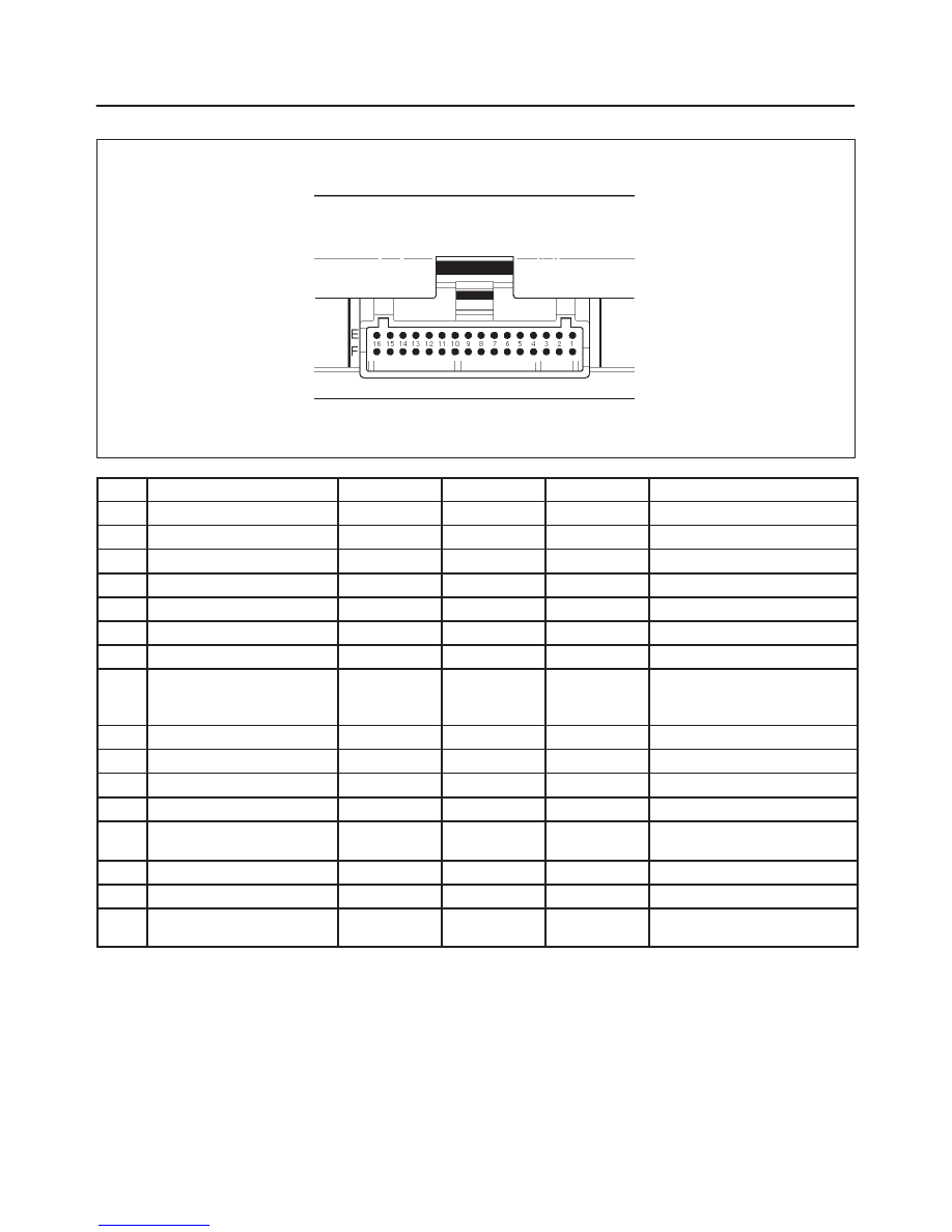
PCM Pinout Table, 32–Pin White Connector – Row ”F”
TS23346
PIN
PIN Function
Wire Color
IGN ON
ENG RUN
Refer To
F1
Not Used
—
—
—
—
F2
Not Used
—
—
—
—
F3
Not Used
—
—
—
—
F4
Not Used
—
—
—
—
F5
Not Used
—
—
—
—
F6
Not Used
—
—
—
—
F7
Not Used
—
—
—
—
F8
Manifold Absolute
Pressure (MAP) Sensor
Input
GRY
~4.7 V
(0 V = 10kPa)
~1.1 V
(5 V =
104kPa)
General Description and
Operation, Manifold Absolute
Pressure
F9
Not Used
—
—
—
—
F10
Not Used
—
—
—
—
F11
Not Used
—
—
—
—
F12
DLC (Digital Input)
—
—
—
Class 2 Serial Data
F13
Injector ”C” Cylinder #4
GRN
B+
B+
General Description and
Operation, Fuel Injector
F14
Not Used
—
—
—
—
F15
Not Used
—
—
—
—
F16
Ignition Feed
RED/BLU
B+
B+
General Description and
Operation
Нет комментариевНе стесняйтесь поделиться с нами вашим ценным мнением.
Текст