Isuzu Rodeo UE. Manual — part 587
8D–196
WIRING SYSTEM
Keyless Entry and Anti–Theft System
General Description
The circuit consists of the starter switch, anti–theft &
keyless entry controller, anti-theft horn, front door and
tailgate key switch (detect and tamper switch), door lock
(& power window) switch, door lock actuator for each
door, engine hood switch, clutch start switch (M/T),
ANTI-THEFT indicator light and mode switch (A/T). The
system operates as follows: After locking the starter
switch and removing the starter key (this sets the alarm),
if the door is unlocked in any way other than with the
proper key, the headlights start flashing, the horn sounds,
and the starter circuit is disabled. (However, the engine
hood and all the doors must be locked and closed.)
Once the system has been placed in the warning or alarm
condition, it can be released only when the starter switch
is shifted from “OFF” to “ACC” by the starter key, or when
the lock of the front door or the tailgate is released (to
activate the detect switch) by the starter key.
Under this system the doors can be locked/unlocked by
merely pressing the remote control buttons without
inserting the ignition key.
Further, when you meet with a robbery, etc. in or near your
vehicle, you can inform people around of the danger via
horn and light by pressing the remote control panic
button. The remote control is effective within the radius of
32.8 ft (10 meters) of your vehicle. This effective zone
may be varied depending on the conditions around.
NOTE: This equipment has been tested and found to
comply with the limits for a Class B digital device,
pursuant to part 15 of the FCC Rules. There limits are
designed to against harmful interference in a residential
installation. This equipment generates, uses and can
radiate radio frequency energy and, if not installed and
used in accordance with the instructions, may cause
harmful interference to radio communications. However,
there is no guarantee that interference will not occur in
a particular installation if this equipment does cause
harmful interference to radio or television reception,
which can be determined by turning the equipment off
and on, the user is encouraged to try to correct the
interference by one or more of the following measures:
-Reorient or relocate the receiving antenna.
-Increase the separation between the equipment and
receiver.
-Connect the equipment into an outlet on a circuit different
from that to which the receiver is connected.
-Consult the dealer or an experienced radio/TV
technician for help.
8D–197
WIRING SYSTEM
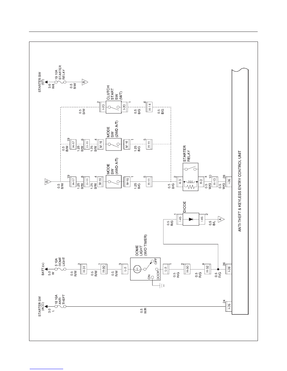
Circuit Diagram–1
D08RX058
8D–198
WIRING SYSTEM
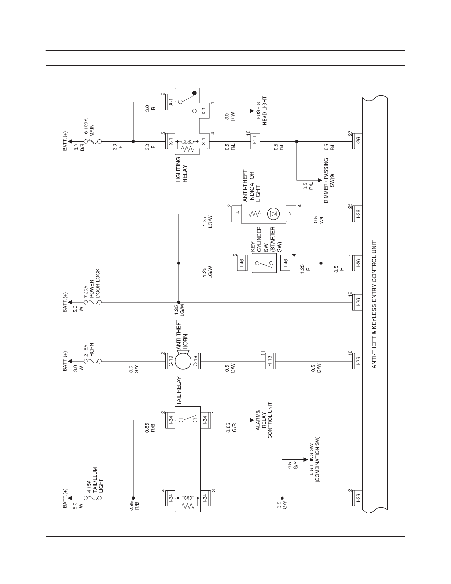
Circuit Diagram–2
D08RX059
8D–199
WIRING SYSTEM
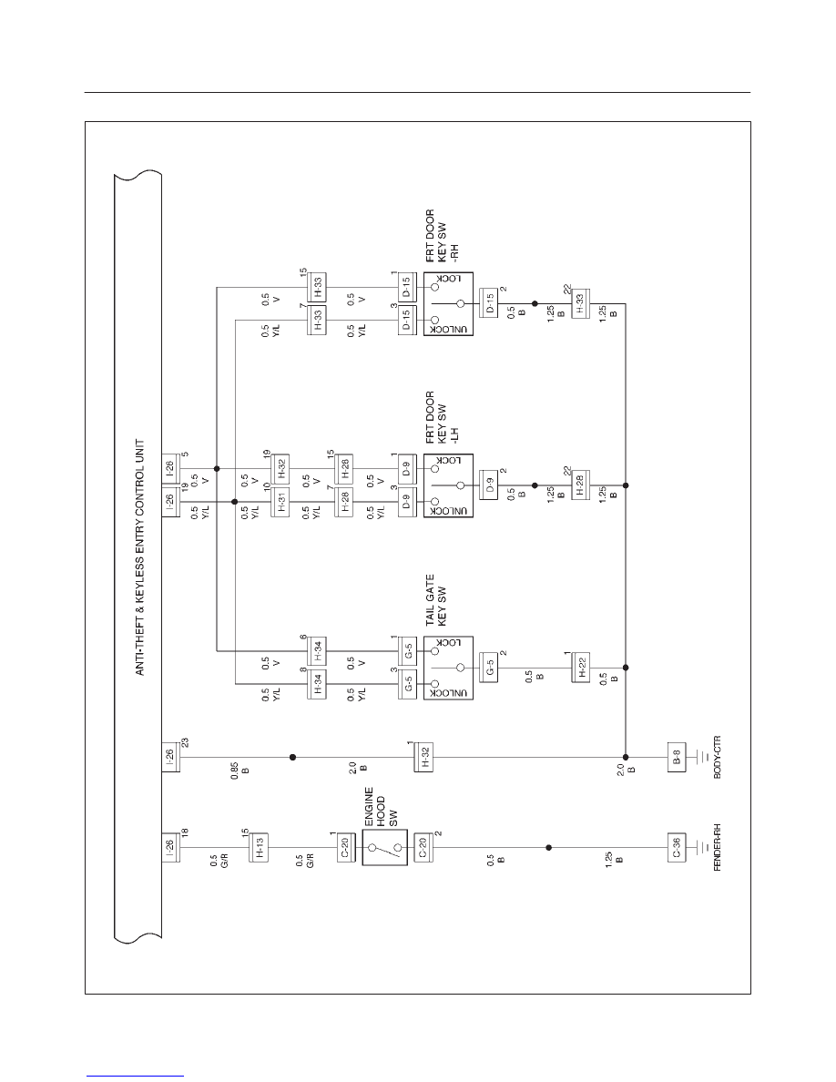
Circuit Diagram–3
D08RX060
Нет комментариевНе стесняйтесь поделиться с нами вашим ценным мнением.
Текст