Isuzu Rodeo UE. Manual — part 285
6A–53
ENGINE MECHANICAL (6VD1 3.2L)
Reassembly
1. Install Spark plug and tighten all the spark plugs to
specified torque.
Torque: 18 N·m (13 lb ft)
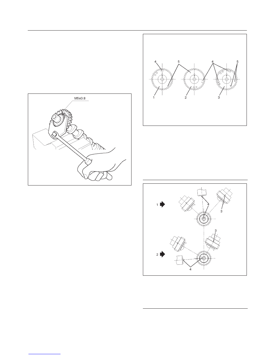
2. Tighten sub gear setting bolt.
1. Use J–42686 gear spring lever to turn sub gear to
right direction until the M5 bolt aligns with the hole
between camshaft driven gear and sub gear.
2. Tighten the M5 bolt to a suitable torque to prevent
the sub gear from moving.
014RW025
3. Install camshaft drive gear assembly and tighten
three bolts to the specified torque.
Torque: 10 N·m (89 lb in)
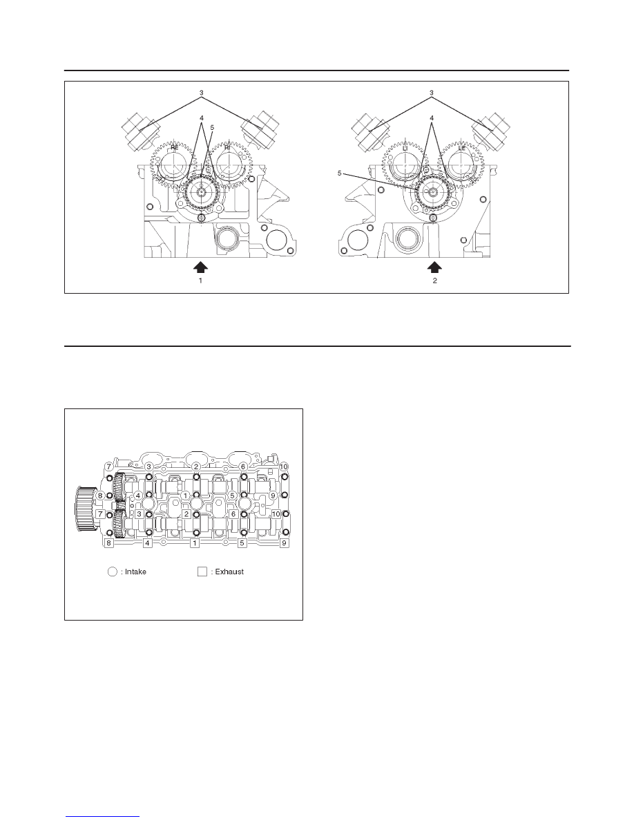
4. Install camshaft assembly and camshaft brackets,
tighten twenty bolts on one side bank to the specified
torque.
1. Apply engine oil to camshaft journal and bearing
surface of camshaft bracket.
2. Align timing mark on intake camshaft (one dot for
right bank, two dots for left bank) and exhaust
camshaft (one dot for right bank, two dots for left
bank) to timing mark on camshaft drive gear (one
dot).
014RW020
Legend
(1) Intake Camshaft Timing Gear for Right Bank
(2) Intake Camshaft Timing Gear for Left Bank
(3) Exhaust Camshaft Timing Gear
(4) Discrimination Mark
LI: Left Bank Intake
RI: Right Bank Intake
LE: Left Bank Exhaust
RE: Right Bank Exhaust
014RW023
Legend
(1) Right Bank Camshaft Drive Gear
(2) Left Bank Camshaft Drive Gear
(3) Timing Mark on Drive Gear
(4) Dowel Pin
6A–54
ENGINE MECHANICAL (6VD1 3.2L)
014RW024
Legend
(1) Right Bank
(2) Left Bank
(3) Alignment Mark on Camshaft Drive Gear
(4) Alignment Mark on Camshaft
(5) Alignment Mark on Retainer
3. Tighten twenty bolts in numerical order on each
bank as shown in the illustration.
Torque: 10 N·m (89 lb in)
014RW031
5. Tighten bolt for camshaft drive gear assembly pulley
to the specified torque.
Torque: 98 N·m (72 lb ft)
6A–55
ENGINE MECHANICAL (6VD1 3.2L)
Valve Spring, Oil Controller, Valve, Valve Guide
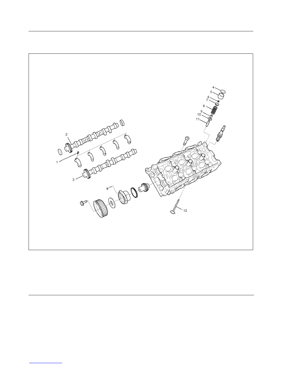
Valve Spring, Oil Controller, Valve, Valve Guide and Associated Parts
014RW039
Legend
(1) Camshaft Bracket Fixing Bolts
(2) Camshaft Assembly Inlet
(3) Camshaft Assembly Exhaust
(4) Shim
(5) Tappet
(6) Split Collar
(7) Spring Upper Seat
(8) Valve Spring
(9) Oil Controller
(10) Spring Lower Seat
(11) Valve Guide
(12) Valve
Disassembly
1. Remove camshaft bracket fixing bolts (1).
2. Remove camshaft assembly (intake).
3. Remove camshaft assembly (Exhaust side).
4. Remove shim (4) and tappet (5).
6A–56
ENGINE MECHANICAL (6VD1 3.2L)
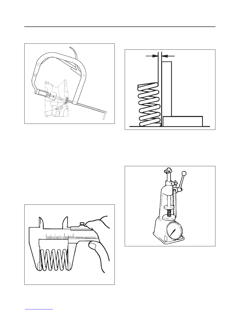
5. Use the J–8062 valve spring compressor and
J–42898 valve spring compressor adapter to remove
split collar.
014RW042
6. Remove valve spring.
7. Remove valve.
8. Remove oil controller and spring lower seat.
9. Remove the valve guide using the J–42899 valve
guide replacer.
Inspection and Repair
Valve Spring
CAUTION: Visually inspect the valve springs and
replace them if damage or abnormal wear is evident.
1. Measure the free height of the springs. The springs
must be replaced if the free height is below the
specified limit.
Standard : 44.6 mm (1.756 in)
Limit : 43.6 mm (1.717 in)
014RS004
2. Measure the valve spring squareness with a steel
square and replace the valve springs if the measured
value exceeds the specified limit.
Limit : 2 mm (0.079 in)
014RS005
3. Using a spring tester to compress the springs to the
installed height, measure the compressed spring
tension, and replace the springs if the measured
tension is below the specified limit.
At installed height: 35.0 mm (1.38 in)
Standard: 196 N (44 lb)
Limit: Less than 181 N (41 lb)
014RS006
Valve Guide
CAUTION: Take care not to damage the valve seat
contact surface, when removing carbon adhering to
the valve head. Carefully inspect the valve stem for
scratchs or abnormal wear. If these conditions are
present, the valve and the valve guide must be
replaced as a set.
Нет комментариевНе стесняйтесь поделиться с нами вашим ценным мнением.
Текст