Isuzu Rodeo UE. Manual — part 435
6E2–495
RODEO 6VD1 3.2L ENGINE DRIVEABILITY AND EMISSIONS
055RW004
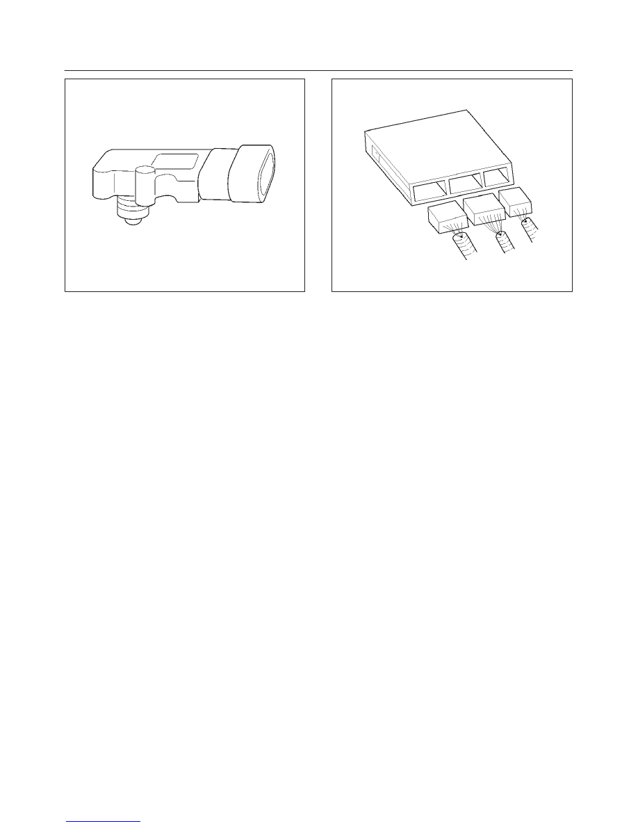
Powertrain Control Module (PCM)
The powertrain control module (PCM) is located in the
passenger compartment below the center console. The
PCM controls the following:
f
Fuel metering system.
f
Transmission shifting (automatic transmission only).
f
Ignition timing.
f
On-board diagnostics for powertrain functions.
The PCM constantly observes the information from
various sensors. The PCM controls the systems that
affect vehicle performance. The PCM performs the
diagnostic function of the system. It can recognize
operational problems, alert the driver through the MIL
(Service Engine Soon lamp), and store diagnostic trouble
codes (DTCs). DTCs identify the problem areas to aid the
technician in making repairs.
f
IPCM-6KT for automatic transmission-equipped
vehicles.
PCM Function
The PCM supplies either 5 or 12 volts to power various
sensors or switches. The power is supplied through
resistances in the PCM which are so high in value that a
test light will not light when connected to the circuit. In
some cases, even an ordinary shop voltmeter will not give
an accurate reading because its resistance is too low.
Therefore, a digital voltmeter with at least 10 megohms
input impedance is required to ensure accurate voltage
readings. Tool J 39200 meets this requirement. The PCM
controls output circuits such as the injectors, IAC, cooling
fan relays, etc., by controlling the ground or the power
feed circuit through transistors or through either of the
following two devices:
f
Output Driver Module (ODM)
f
Quad Driver Module (QDM)
0005
PCM Components
The PCM is designed to maintain exhaust emission levels
to government mandated standards while providing
excellent driveability and fuel efficiency. The PCM
monitors numerous engine and vehicle functions via
electronic sensors such as the throttle position (TP)
sensor, heated oxygen sensor (HO2S), and vehicle
speed sensor (VSS). The PCM also controls certain
engine operations through the following:
f
Fuel injector control
f
Ignition control module
f
Knock sensor
f
Automatic transmission shift functions
f
Cruise control
f
Evaporative emission (EVAP) purge
f
A/C clutch control
PCM Voltage Description
The PCM supplies a buffered voltage to various switches
and sensors. It can do this because resistance in the
PCM is so high in value that a test light may not illuminate
when connected to the circuit. An ordinary shop
voltmeter may not give an accurate reading because the
voltmeter input impedance is too low. Use a 10-megohm
input impedance digital voltmeter (such as J 39200) to
assure accurate voltage readings.
The input/output devices in the PCM include
analog-to-digital converters, signal buffers, counters,
and special drivers. The PCM controls most components
with electronic switches which complete a ground circuit
when turned “ON.” These switches are arranged in
groups of 4 and 7, called either a surface-mounted quad
driver module (QDM), which can independently control up
to 4 output terminals, or QDMs which can independently
control up to 7 outputs. Not all outputs are always used.
PCM Input/Outputs
Inputs – Operating Conditions Read
f
Air Conditioning “ON” or “OFF”
6E2–496
RODEO 6VD1 3.2L ENGINE DRIVEABILITY AND EMISSIONS
f
Engine Coolant Temperature
f
Crankshaft Position
f
Exhaust Oxygen Content
f
Electronic Ignition
f
Manifold Absolute Pressure
f
Battery Voltage
f
Throttle Position
f
Vehicle Speed
f
Fuel Pump Voltage
f
Power Steering Pressure
f
Intake Air Temperature
f
Mass Air Flow
f
Engine Knock
f
Camshaft Position
Outputs – Systems Controlled
f
EVAP Canister Purge
f
Exhaust Gas Recirculation (EGR)
f
Ignition Control
f
Fuel Control
f
Idle Air Control
f
Electric Fuel Pump
f
Air Conditioning
f
Diagnostics
– Malfunction Indicator Lamp
– Data Link Connector (DLC)
– Data Output
f
Transmission Control Module
f
Alternator Gain Control
PCM Service Precautions
The PCM is designed to withstand normal current draws
associated with vehicle operation. Avoid overloading any
circuit. When testing for opens and shorts, do not ground
or apply voltage to any of the PCM’s circuits unless
instructed to do so. These circuits should only be tested
using digital voltmeter J 39200. The PCM should remain
connected to the PCM or to a recommended breakout
box.
Reprogramming The PCM
Reprogramming of the PCM without removing it from the
vehicle . This provides a flexible and cost-effective
method of making changes in software calibrations.
Refer to the latest Techline information on
reprogramming or flashing procedures.
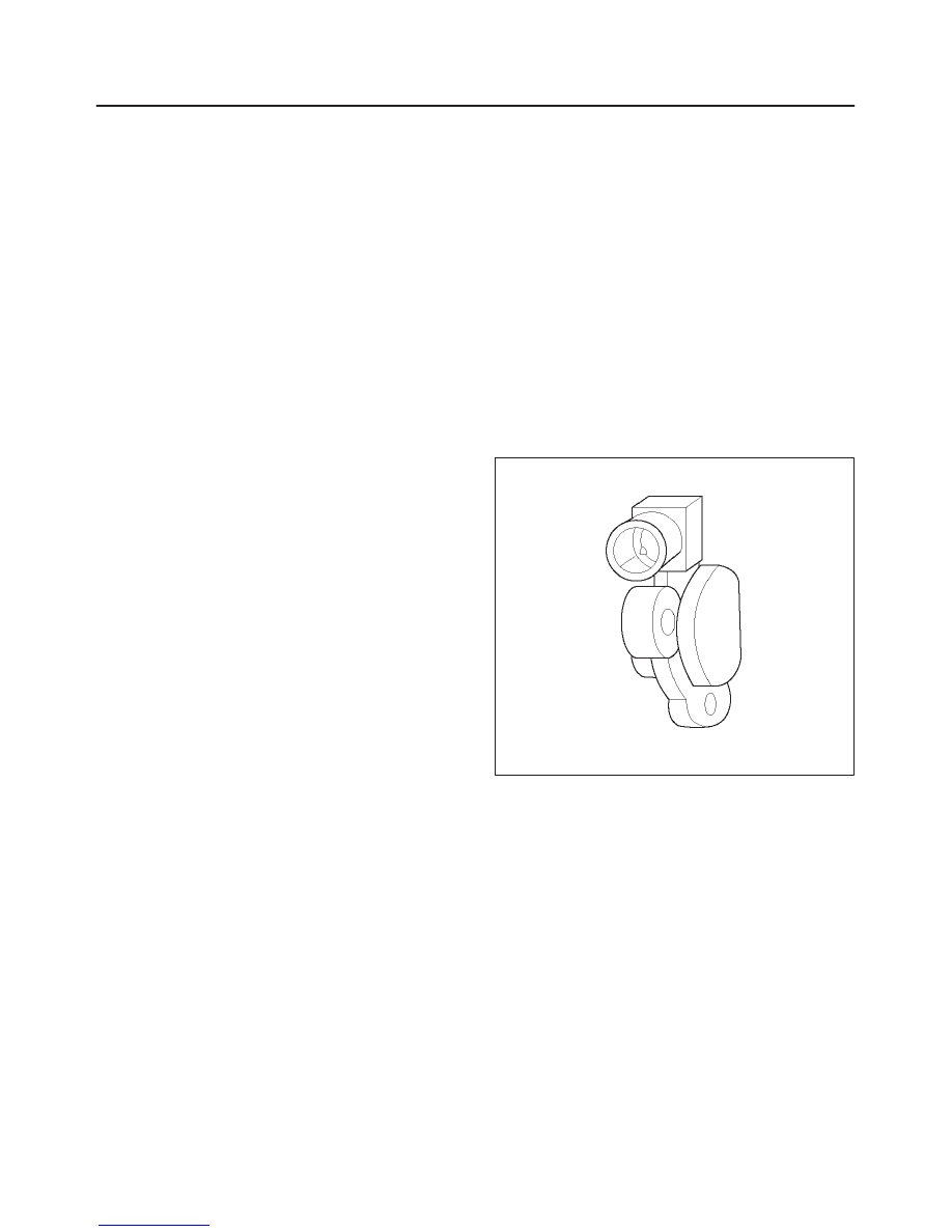
Throttle Position (TP) Sensor
The throttle position (TP) sensor is a potentiometer
connected to the throttle shaft on the throttle body. The
PCM monitors the voltage on the signal line and
calculates throttle position. As the throttle valve angle is
changed (accelerator pedal moved), the TP sensor signal
also changes. At a closed throttle position, the output of
the TP sensor is low. As the throttle valve opens, the
output increases so that at wide open throttle (WOT), the
output voltage should be above 4 volts.
The PCM calculates fuel delivery based on throttle valve
angle (driver demand). A broken or loose TP sensor may
cause intermittent bursts of fuel from an injector and
unstable idle because the PCM thinks the throttle is
moving. A hard failure in the TP sensor 5-volt reference
or signal circuits will set either a DTC P0122 or DTC
P0123. A hard failure with the TP sensor ground circuit
may set DTC P0123 and DTC P0112. Once a DTC is set,
the PCM will use an artificial default value based on
engine RPM and mass air flow for the throttle position,
and some vehicle performance will return. A high idle
may result when either DTC P0122 or DTC P0123 is set.
The PCM can detect intermittent TP sensor faults. DTC
P1121 or DTC P1122 will set if an intermittent high or low
circuit failure is being detected. The PCM can also detect
a shifted TP sensor. The PCM monitors throttle position
and compares the actual TP sensor reading to a
predicted TP value calculated from engine speed. If the
PCM detects an out-of-range condition, DTC P0121 will
be set.
0021
Transmission Fluid Temperature (TFT)
Sensor
The transmission fluid temperature sensor is a thermistor
which changes its resistance based on the temperature of
the transmission fluid. For a complete description of the
TFT sensor, refer to
4L30-E Automatic Transmission
Diagnosis.
A failure in the TFT sensor or associated wiring will cause
DTC P0712 or DTC P0713 to set. In this case, engine
coolant temperature will be substituted for the TFT
sensor value and the transmission will operate normally.
Transmission Range Switch
IMPORTANT:
The vehicle should not be driven with the
transmission range switch disconnected; idle quality will
be affected.
The four inputs from the transmission range switch
indicate to the PCM which position is selected by the
transmission selector lever. This information is used for
ignition timing, EVAP canister purge, EGR and IAC valve
operation.
6E2–497
RODEO 6VD1 3.2L ENGINE DRIVEABILITY AND EMISSIONS
For more information on the transmission on the
transmission range switch, refer to
4L30-E Automatic
Transmission.
Vehicle Speed Sensor (VSS)
The PCM determines the speed of the vehicle by
converting a plusing voltage signal from the vehicle speed
sensor (VSS) into miles per hour. The PCM uses this
signal to operate the cruise control, speedometer, and the
TCC and shift solenoids in the transmission. For more
information on the TCC and shift solenoids, refer to
4L30-E Automatic Transmission.
0008
Use of Circuit Testing Tools
Do not use a test light to diagnose the powertrain
electrical systems unless specifically instructed by the
diagnostic procedures. Use Connector Test Adapter Kit J
35616 whenever diagnostic procedures call for probing
connectors.
Aftermarket Electrical and Vacuum
Equipment
Aftermarket (add-on) electrical and vacuum equipment is
defined as any equipment which connects to the vehicle’s
electrical or vacuum systems that is installed on a vehicle
after it leaves the factory. No allowances have been
made in the vehicle design for this type of equipment.
NOTE: No add-on vacuum equipment should be added
to this vehicle.
NOTE: Add-on electrical equipment must only be
connected to the vehicle’s electrical system at the battery
(power and ground).
Add-on electrical equipment, even when installed to
these guidelines, may still cause the powertrain system to
malfunction. This may also include equipment not
connected to the vehicle electrical system such as
portable telephones and radios. Therefore, the first step
in diagnosing any powertrain problem is to eliminate all
aftermarket electrical equipment from the vehicle. After
this is done, if the problem still exists, it may be diagnosed
in the normal manner.
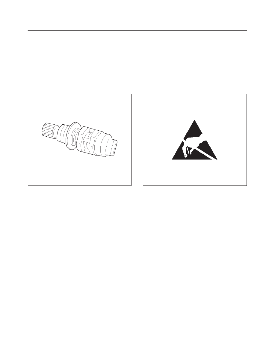
Electrostatic Discharge Damage
Electronic components used in the PCM are often
designed to carry very low voltage. Electronic
components are susceptible to damage caused by
electrostatic discharge. Less than 100 volts of static
electricity can cause damage to some electronic
components. By comparison, it takes as much as 4000
volts for a person to feel even the zap of a static
discharge.
TS23793
There are several ways for a person to become statically
charged. The most common methods of charging are by
friction and induction.
f
An example of charging by friction is a person sliding
across a vehicle seat.
f
Charge by induction occurs when a person with well
insulated shoes stands near a highly charged object
and momentary touches ground. Charges of the
same polarity are drained off leaving the person
highly charged with the opposite polarity. Static
charges can cause damage, therefore it is important
to use care when handling and testing electronic
components.
NOTE: To prevent possible electrostatic discharge
damage, follow these guidelines:
f
Do not touch the PCM connector pins or soldered
components on the PCM circuit board.
f
Do not touch the knock sensor module component
leads.
f
Do not open the replacement part package until the
part is ready to be installed.
f
Before removing the part from the package, ground
the package to a known good ground on the vehicle.
f
If the part has been handled while sliding across the
seat, while sitting down from a standing position, or
while walking a distance, touch a known good ground
before installing the part.
6E2–498
RODEO 6VD1 3.2L ENGINE DRIVEABILITY AND EMISSIONS
Upshift Lamp
Refer to
Manual Transmission.
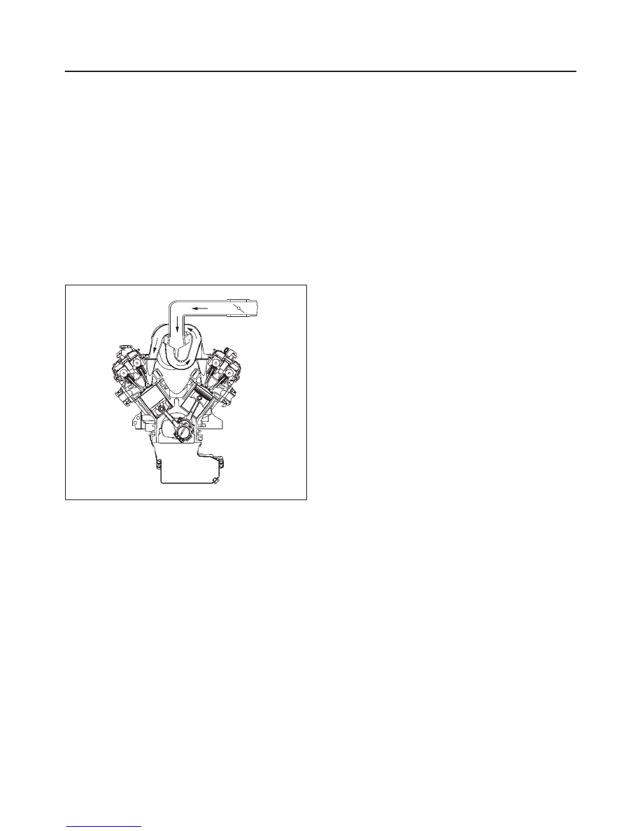
General Description (Air Induction)
Air Induction System
The air induction system filters contaminants from the
outside air, and directs the progress of the air as it is
drawn into the engine. A remote-mounted air cleaner
prevents dirt and debris in the air from entering the
engine. The air duct assembly routes filtered air to the
throttle body. Air enters the engine by to following steps:
1. Through the throttle body.
2. Into the common chamber.
3. Through the cylinder head intake ports.
4. Into the cylinders.
055RV010
General Description (Fuel Metering)
Acceleration Mode
The PCM provides extra fuel when it detects a rapid
increase in the throttle position and the air flow.
Accelerator Controls
The accelerator control system is a cable-type system
with specific linkage adjustments.
Refer to
Cable Adjustment.
Battery Voltage Correction Mode
When battery voltage is low, the PCM will compensate for
the weak spark by increasing the following:
f
The amount of fuel delivered.
f
The idle RPM.
f
Ignition dwell time.
CMP Signal
The PCM uses this signal to determine the position of the
number 1 piston during its power stroke, allowing the
PCM to calculate true sequential multiport fuel injection
(SFI). Loss of this signal will set a DTC P0341. If the CMP
signal is lost while the engine is running, the fuel injection
system will shift to a calculated sequential fuel injection
based on the last fuel injection pulse, and the engine will
continue to run. The engine can be restarted and will run
in the calculated sequential mode as long as the fault is
present, with a 1-in-6 chance of being correct.
Clear Flood Mode
Clear a flooded engine by pushing the accelerator pedal
down all the way. The PCM then de-energizes the fuel
injectors. The PCM holds the fuel injectors de-energized
as long as the throttle remains above 80% and the engine
speed is below 800 RPM. If the throttle position becomes
less than 80%, the PCM again begins to pulse the
injectors “ON” and “OFF,” allowing fuel into the cylinders.
Deceleration Mode
The PCM reduces the amount of fuel injected when it
detects a decrease in the throttle position and the air flow.
When deceleration is very fast, the PCM may cut off fuel
completely for short periods.
Engine Speed/Vehicle Speed/Fuel Disable
Mode
The PCM monitors engine speed. It turns off the fuel
injectors when the engine speed increase above 6400
RPM. The fuel injectors are turned back on when engine
speed decreases below 6150 RPM.
Fuel Cutoff Mode
No fuel is delivered by the fuel injectors when the ignition
is “OFF.” This prevents engine run-on. In addition, the
PCM suspends fuel delivery if no reference pulses are
detected (engine not running) to prevent engine flooding.
Fuel Injector
The sequential multiport fuel injection (SFI) fuel injector is
a solenoid-operated device controlled by the PCM. The
PCM energizes the solenoid, which opens a valve to allow
fuel delivery.
The fuel is injected under pressure in a conical spray
pattern at the opening of the intake valve. Excess fuel not
used by the injectors passes through the fuel pressure
regulator before being returned to the fuel tank.
Нет комментариевНе стесняйтесь поделиться с нами вашим ценным мнением.
Текст