Isuzu Rodeo UE. Manual — part 409

6E2–391
RODEO 6VD1 3.2L ENGINE DRIVEABILITY AND EMISSIONS
Reviewing the Failure Records vehicle mileage since the
diagnostic test last failed may help determine how often
the condition that caused the DTC to be set occurs. This
may assist in diagnosing the condition.
Test Description
Number(s) below refer to the step number(s) on the
Diagnostic Chart.
3. A condition that affects other heated oxygen sensors
indicates probable contamination. To avoid
damaging replacement sensors, correct the
condition which caused the contamination before
replacing the affected sensors.
5. This step checks for conditions which may cause the
heated oxygen sensor to appear faulty. Correct any
of the described conditions if present.
8. To avoid damaging replacement sensors, correct the
condition which caused the contamination before
replacing the affected sensors.
DTC P1154 –HO2S Transition Time Ratio Bank 2 Sensor 1
Step
Action
Value(s)
Yes
No
1
Was the “On-Board Diagnostic (OBD) System Check”
performed?
—
Go to
Step 2
Go to
OBD
System
Check
2
IMPORTANT: If any other DTCs are set (except P1133
and/or P1134), refer to those DTCs before proceeding
with this diagnostic chart.
1. Idle the engine at operating temperature.
2. Operate the vehicle within parameters specified
under “Conditions for Setting the DTC” criteria
included in Diagnostic Support.
3. Using a Tech 2, monitor “DTC” info for DTC P1154
until the DTC P1154 test runs.
Note the test result.
Does Tech 2 indicate DTC failed this ignition?
—
Go to
Step 3
Refer to
Diagnostic
Aids
3
Did the Tech 2 also indicate P1133, and/or P1134 test
failed?
—
Go to
Step 17
Go to
Step 4
4
Check for leaks at the exhaust pipe joints.
Are the joints leaking?
—
Go to
Step 5
Go to
Step 6
5
Tighten the U-bolt nuts at the leaking joints.
Is your action complete?
—
Go to
Step 2
—
6
Check for gaskets that are damaged or improperly
installed.
Are there damaged or misaligned gaskets?
—
Go to
Step 7
Go to
Step 8
7
1. Replace the damaged gaskets.
2. Align the connections.
3. Tighten the connections.
Is your action complete?
—
Go to
Step 2
—
8
Check for loose exhaust flange connections.
Are the flange connections loose?
—
Go to
Step 9
Go to
Step 10
9
Tighten the stud nuts or bolts to specifications.
Is your action complete?
—
Go to
Step 2
—
10
Check for burned or corroded exhaust pipes.
Are the exhaust pipes burned or corroded?
—
Go to
Step 11
Go to
Step 12
11
Replace the exhaust pipes, as required.
Is your action complete?
—
Go to
Step 2
—

6E2–392
RODEO 6VD1 3.2L ENGINE DRIVEABILITY AND EMISSIONS
DTC P1154 –HO2S Transition Time Ratio Bank 2 Sensor 1
(Cont'd)
Step
No
Yes
Value(s)
Action
12
Check for leaks at the exhaust manifold.
Are there leaks at the exhaust manifold?
—
Go to
Step 13
Go to
Step 14
13
Tighten the bolts to specifications or replace the
manifold if necessary.
Is your action complete?
—
Go to
Step 2
—
14
Visually/physically inspect the following items:
f
Ensure that the Bank 2 HO2S 1 is securely
installed.
f
Check for corrosion on terminals.
f
Check terminal tension (at Bank 2 HO2S 1 and at
the PCM).
f
Check for damaged wiring.
Was a problem found in any of the above areas?
—
Go to
Step 18
Go to
Step 15
15
1. Disconnect Bank 2 HO2S 1.
2. Ignition “ON.”
3. Using a DVM at the PCM side of the HO2S 1
connector, measure the voltage between the high
signal circuit and ground.
4. Also measure the voltage between the low signal
circuit and ground.
Are both voltages in the specified range?
3-4V
Go to
Step
16
Go to
Step 19
16
1. With Bank 2 HO2S 1 disconnected, jumper the high
and low (PCM side) signal circuits to ground.
2. Ignition “ON.”
3. Using a Tech 2, monitor the Bank 2 HO2S 1 voltage.
Does the Tech 2 indicate less than 10 mV and
immediately return to about 450 mV when the jumper is
removed?
—
Go to
Step 21
Go to
Step 22
17
Replace affected heated oxygen sensors.
NOTE: Before replacing sensors, the cause of the
contamination must be determined and corrected.
f
Fuel contamination.
f
Use of improper RTV sealant.
f
Engine oil/coolant consumption.
Is the action complete?
—
Verify repair
—
18
Repair condition as necessary.
Is the action complete?
—
Verify repair
—
19
Check for faulty PCM connections or terminal damage.
Is the action complete?
—
Verify repair
Go to
Step 20
20
Repair open, short or grounded signal circuit.
Is the action complete?
—
Verify repair
—

6E2–393
RODEO 6VD1 3.2L ENGINE DRIVEABILITY AND EMISSIONS
DTC P1154 –HO2S Transition Time Ratio Bank 2 Sensor 1
(Cont'd)
Step
No
Yes
Value(s)
Action
21
Replace Bank 2 HO2S 1.
Is the action complete?
—
Verify repair
—
22
Replace the PCM.
IMPORTANT: The replacement PCM must be
programmed. Refer to
On-Vehicle Service in
Powertrain Control Module and Sensors for
procedures.
And also refer to latest Service Bulletin.
Check to see if the Latest software is released or not.
And then Down Load the LATEST PROGRAMMED
SOFTWARE to the replacement PCM.
Is the action complete?
—
Verify repair
—
6E2–394
RODEO 6VD1 3.2L ENGINE DRIVEABILITY AND EMISSIONS
Diagnostic Trouble Code (DTC) P1171 Fuel System Lean Dueing Acceleration
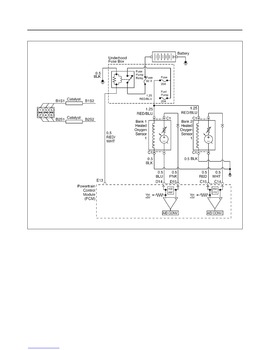
D06RX023
Circuit Description
The powertrain control module (PCM) internal circuitry
can identify if the vehicle fuel system is capable of
supplying adequate amounts of fuel during heavy
acceleration (power enrichment). The PCM monitors the
voltage of the oxygen sensor during power enrichment.
When a power enrichment mode of operation is
requested during “closed loop” operation (by heavy
acceleration), the PCM will provide more fuel to the
engine. Under these conditions the PCM should detect a
“rich” condition (high oxygen sensor voltage). If this “rich”
exhaust is not detected at this time, a DTC P1171 will set.
A plugged fuel filter, restricted fuel line, restricted in-tank
filter or defective fuel pump can prevent adequate amouts
of fuel from being supplied during power enrichment
mode.
Conditions for Setting the DTC
f
No related DTCs.
f
Engine is operating in “closed loop power enrichment”
mode for 3 seconds.
f
Engine coolant temperature is above 60
°
C (140
°
F).
f
While in “power enrichment” mode the oxygen sensor
voltage remains below 400 mV for 3 seconds.
Action Taken When the DTC Sets
f
The PCM will illuminate the malfunction indicator lamp
(MIL) the first the fault is detected.
f
The PCM will store conditions which were present
when the DTC was set as Freeze Frame and in the
Failure Records data.
Conditions for Clearing the MIL/DTC
f
The PCM will turn the MIL “OFF” on the third
consecutive trip cycle during which the diagnostic has
been run and the fault condition is no longer present.
f
A history DTC P1171 will clear after 40 consecutive
warm-up cycles have occurred without a fault.
Нет комментариевНе стесняйтесь поделиться с нами вашим ценным мнением.
Текст