Isuzu Rodeo UE. Manual — part 306
6D3–5
STARTING AND CHARGING SYSTEM (6VD1 3.2L)
Starter
Removal
1. Battery ground cable.
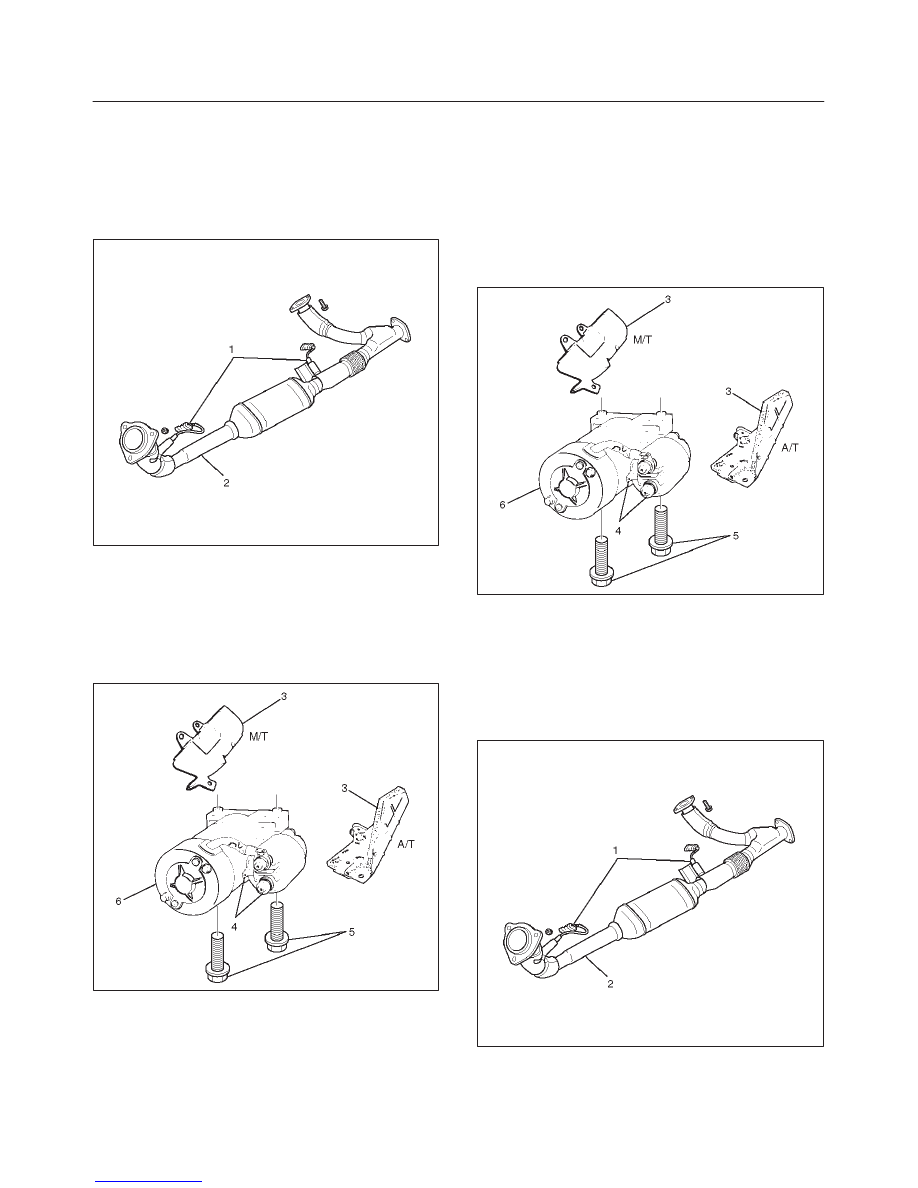
2. Disconnect Heated O
2
Sensor connector (1).
3. Remove exhaust front left pipe(2).
035RW016
4. Remove heat protector(3).
5. Disconnect starter wiring connector from terminals
“B” and “S”(4).
6. Remove starter assembly mounting bolts on inside
and outside(5).
7. Remove starter assembly toward the bottom of
engine(6).
065RW001
Installation
1. Install starter assembly(6).
2. Install mounting bolts and tighten bolts to specified
torque(5).
Torque: 40 N·m (30 lb ft)
3. Reconnect the connectors to terminals “B” and “S”
and tighten Terminals “B” to specified torque.
Torque: 9 N·m (80 lb in)
4. Install heat protector(3).
065RW001
5. Install exhaust front left pipe and tighten bolts and
nuts to specified torque(2).
Stud Nuts
Torque: 67 N·m (49 lb ft)
Nuts
Torque: 43 N·m (32 lb ft)
6. Connect Heated O
2
Sensor connector (1).
035RW016
7. Reconnect the battery ground cable.
6D3–6
STARTING AND CHARGING SYSTEM (6VD1 3.2L)
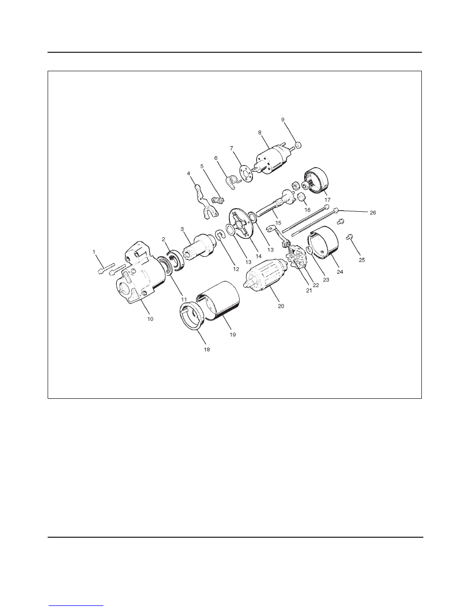
Disassembled View
065RW002
Legend
(1) Bolt (2 pcs)
(2) Ball Bearing
(3) Pinion
(4) Shift Lever
(5) Dust Cover
(6) Torsion Spring
(7) Dust Cover
(8) Magnetic Switch
(9) Nut
(10) Gear Case
(11) Bearing Cover
(12) E–ring
(13) Thrust Washer (2)
(14) Center Bracket
(15) Pinion Shaft
(16) Planet Gear (3)
(17) Internal Gear
(18) Center Bracket (A)
(19) Yoke Assembly
(20) Armature
(21) Brush
(22) Brush Holder
(23) Thrust Washer
(24) Rear Cover
(25) Screw (2 pcs)
(26) Through Bolt (2 pcs)
6D3–7
STARTING AND CHARGING SYSTEM (6VD1 3.2L)
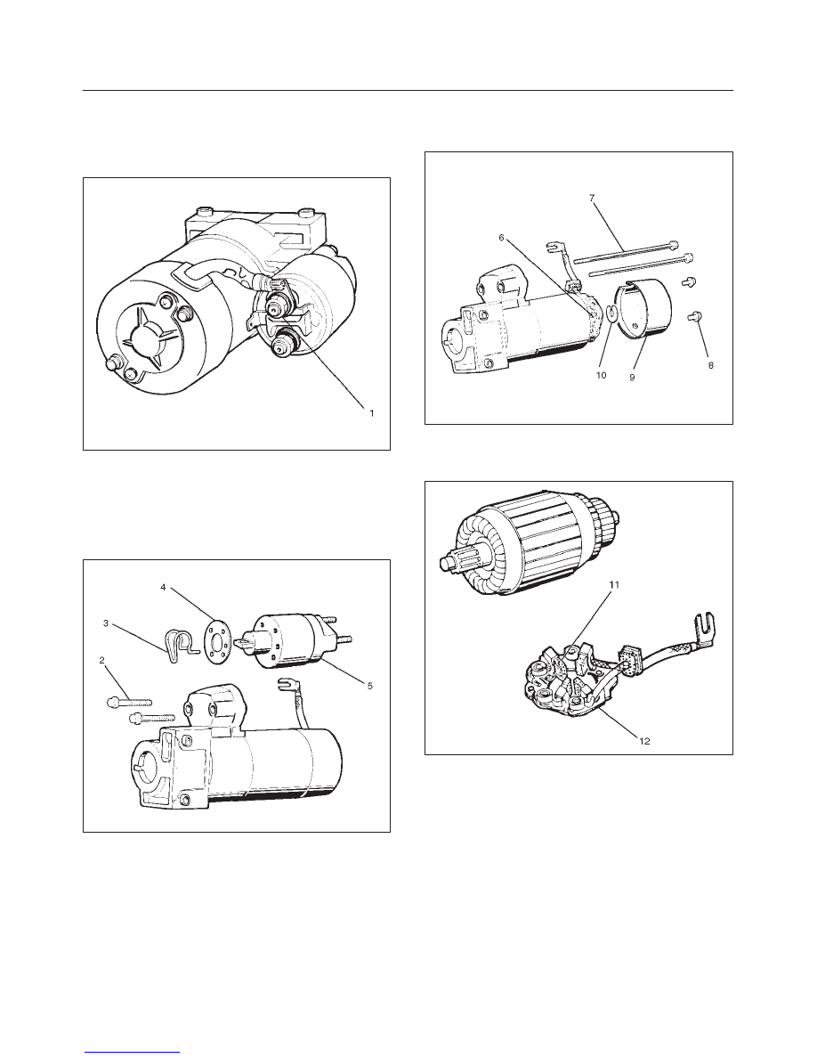
Disassembly
1. Loosen the nut(1) on terminal “M” of magnetic switch
and disconnect the connector cable.
2. Remove bolt (2 pcs) (2).
065RW003
3. Remove magnetic switch(5).
4. Remove dust cover(4).
5. Remove torsion spring bolts, then the magnetic
switch assembly.
6. Remove torsion spring(3) from magnetic switch
assembly(5).
065RW004
7. Remove screw (2 pcs) (8).
8. Remove through bolt (2 pcs) (7).
9. Remove screws and through bolts, then the rear
cover(9) then remove thrust washer(10).
10. Remove brush holder(6).
065RW005
11. Raise a brush spring to detach brushes (4 pcs) from
the commutator face and pull off the brush holder(12)
and brush(11).
065RW006
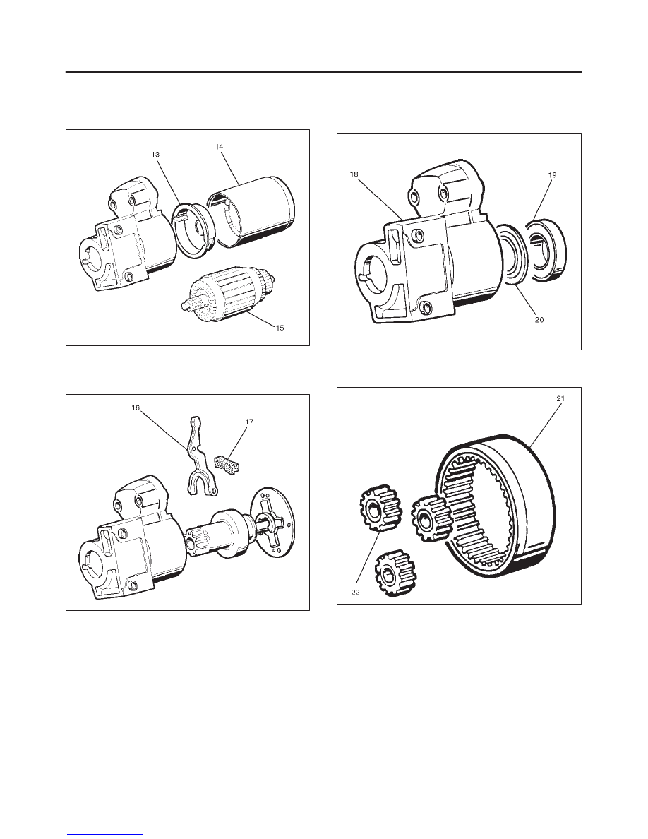
12. Remove yoke assembly(14).
13. Remove armature(15).
14. Pull off the yoke assembly, then remove armature,
washer and center bracket.(A) (13).
6D3–8
STARTING AND CHARGING SYSTEM (6VD1 3.2L)
NOTE: In disassembling the yoke assembly, hold the
armature and pull off slowly the yoke assembly. Because
of strong magnetic force, avoid placing a metallic part
near armature.
065RW007
15. Remove dust cover(17).
16. Remove a dust cover and shift lever(16) from the gear
case.
065RW008
17. Remove ball bearing(19).
18. Remove bearing cover(20).
19. Remove a ball bearing and bearing cover from the
gear case(18).
065RW021
20. Internal gear(21).
21. Remove internal gear and planet gear(3) (22).
065RW009
Нет комментариевНе стесняйтесь поделиться с нами вашим ценным мнением.
Текст