Isuzu Rodeo UE. Manual — part 315
6E2–15
RODEO 6VD1 3.2L ENGINE DRIVEABILITY AND EMISSIONS
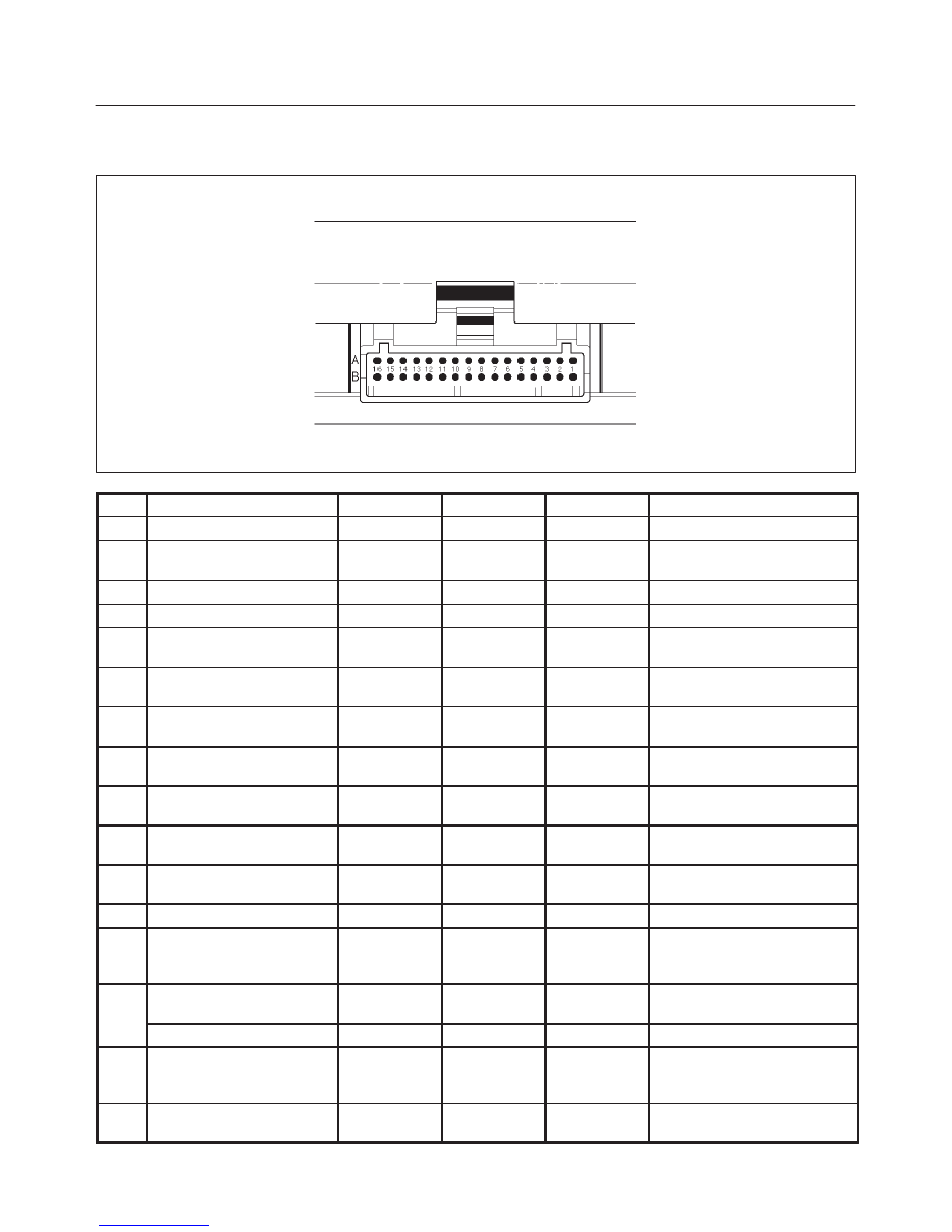
PCM Pinouts
PCM Pinout Table, 32-Way Red Connector – Row “A”
TS23344
PIN
PIN Function
Wire Color
IGN ON
ENG RUN
Refer To
A1
5 Volt Reference “A”
RED
5.0 V
5.0 V
Appropriate Sensor
A2
Knock Sensor
YEL
0.0 V
0.0 V
General Description and
Operation, Knock Sensor
A3
Not Used
A4
Battery Feed (ECM Fuse)
RED/WHT
B+
B+
Chassis Electrical
A5
Idle Air Control (IAC) “A”
High
BLU
B+/0.8 V
B+/0.8 V
General Description and
Operation, IAC
A6
IAC “A” Low
BLU/WHT
B+/0.8 V
B+/0.8 V
General Description and
Operation, IAC
A7
IAC “B” Low
BLU/BLK
B+/0.8 V
B+/0.8 V
General Description and
Operation, IAC
A8
IAC “B” High
BLU/RED
B+/0.8 V
B+/0.8 V
General Description and
Operation, IAC
A9
Automatic Transmission
Fluid (ATF) Lamp
ORN/BLK
B+
B+
Automatic Transmission
(4L30E)
A10
Winter Lamp
PNK/GRN
B+
B+
Automatic Transmission
(4L30E)
A11
Power Lamp
PNK/WHT
B+
B+
Automatic Transmission
(4L30E)
A12
Not Used
A13
Malfunction Indicator
(Check Engine or MIL)
Lamp
WHT/GRN
0.0 V
B+
Chassis Electrical
A14
“Check Transmission” (AT)
Lamp Driver
VIO
B+
B+
Chassis Electrical
Up shift light (MT)
YEL/GRN
B+
B+
Chassis Electrical
A15
EVAP Canister Purge
Signal
RED/BLU
B+
5.7 V
General Description and
Operation, EVAP Emission
Control System
A16
Band Apply
YEL/BLK
B+
B+
Automatic Transmission
(4L30E)
6E2–16
RODEO 6VD1 3.2L ENGINE DRIVEABILITY AND EMISSIONS
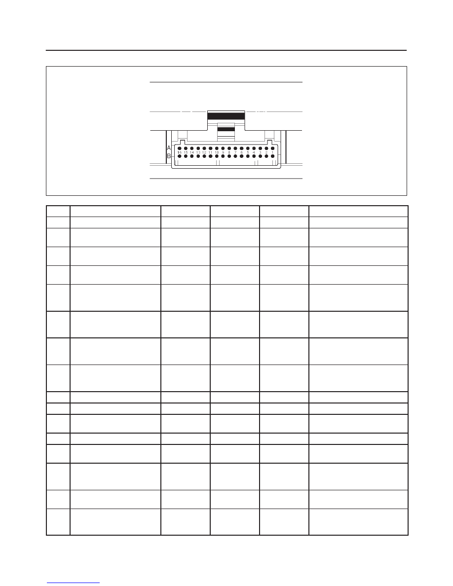
PCM Pinout Table, 32-Way Red Connector – Row “B”
TS23344
PIN
PIN Function
Wire Color
IGN ON
ENG RUN
Refer To
B1
5 Volt Reference “B”
BLU/ORN
5.0 V
5.0 V
Appropriate Sensor
B2
Ignition coil #4
RED/WHT
0.0 V
0.1 V
General Description and
Operation, ICM
B3
Ignition coil #2
RED/BLK
0.0 V
0.1 V
General Description and
Operation, ICM
B4
Ignition coil #6
RED/GRN
0.0 V
0.1 V
General Description and
Operation, ICM
B5
Fuel Level Sensor
ORN/GRN
1.8 V
(Tank empty)
1.8 V
(Tank empty)
General Description and
Operation, Enhanced EVAP
System
B6
Fuel Tank Pressure
Sensor
GRY
1.5 V
(Ambient
pressure)
1.5 V
(Ambient
pressure)
General Description and
Operation, Enhanced EVAP
System
B7
Exhaust Gas Recirculation
(EGR)
YEL/RED
0.6 V
0.6 V
General Description and
Operation, Linear EGR
Control
B8
Intake Air Temperature
(IAT) Sensor
YEL/GRN
≈
3 V
(depends on
temperature)
≈
3 V
(depends on
temperature)
General Description and
Operation, IAT
B9
Not Used
—
—
—
—
B10
Not Used
—
—
—
—
B11
Power Steering Pressure
(PSP) Switch
GRN/YEL
B+
B+
General Description and
Operation, PSP
B12
Illuminated Switch
GRN/YEL
B+
B+
Chassis Electrical
B13
Class 2 Data
ORN/BLK
0.0 V
0.0 V
Diagnosis, Class 2 Serial
Data
B14
A/C Clutch
GRY/RED
B+
(A/C OFF)
B+
(A/C OFF)
General Description and
Operation, A/C Clutch Circuit
Operation
B15
Low Fuel Lamp
PNK
B+
(Lamp OFF)
B+
(Lamp OFF)
—
B16
Fuel Gauge PWM
YEL/RED
B+
Switching
from 13.9 to
14.3 V
General Description and
Operation, Enhanced EVAP
System
6E2–17
RODEO 6VD1 3.2L ENGINE DRIVEABILITY AND EMISSIONS
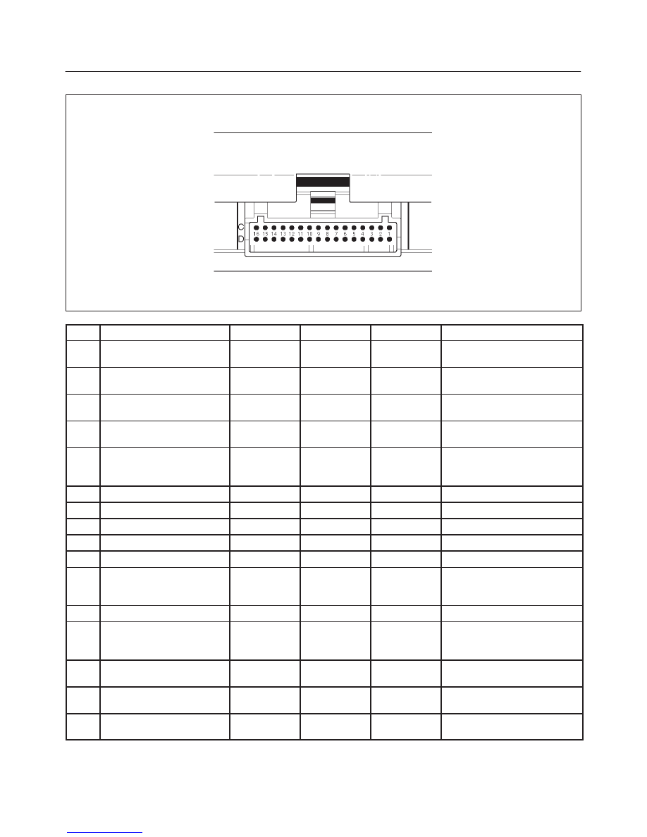
PCM Pinout Table, 32-Way White Connector – Row “C”
TS23345
PIN
PIN Function
Wire Color
IGN ON
ENG RUN
Refer To
C1
Injector Cylinder #4
GRN/RED
B+
B+
General Description and
Operation, Fuel Injector
C2
Shift “B” Solenoid
BRN/BLK
0.0 V
0.0 V
Automatic Transmission
(4L30E)
C3
Injector Cylinder #6
GRN/YEL
B+
B+
General Description and
Operation, Fuel Injector
C4
Ignition Control (IC)
Cylinder #1
RED
0.0 V
0.1 V
General Description and
Operation, Fuel Injector
C5
Crankshaft Position
Sensor, “A” Circuit
YEL
0.3 V
2.2 V
General Description and
Operation, Crankshaft
Position Sensor
C6
Not Used
—
—
—
—
C7
PCM Ground
BLK/WHT
0.0 V
0.0 V
Chassis Electrical
C8
PCM Ground
BLK/RED
0.0 V
0.0 V
Chassis Electrical
C9
PCM Ground
BLK/BLU
0.0 V
0.0 V
Chassis Electrical
C10
Tachometer
BLK/RED
8.8 V
10.0 (at idle)
Chassis Electrical
C11
Variable Intake Manifold
WHT/BLU
0.0 V
0, B+ (More
than 3600
rpm)
Manual Transmission
C12
Rear Defogger Relay
RED/WHT
B+
B+
Chassis Electrical
C13
Canister Cut Valve
BRN/WHT
6.0 V
(Tank empty)
5.7 V
(Tank empty)
General Description and
Operation, Enhanced EVAP
system
C14
Bank 2 HO2S 1 High
WHT
0.3 V
0.0-0.8 V
General Description and
Operation, Fuel HO2S 1
C15
Bank 2 HO2S 1 Low
RED
0.0 V
0.1 V
General Description and
Operation, Fuel HO2S 1
C16
Bank 2 HO2S 2 High
ORN/BLU
0.3 V
0.7 V
General Description and
Operation, Catalyst HO2S 2
6E2–18
RODEO 6VD1 3.2L ENGINE DRIVEABILITY AND EMISSIONS
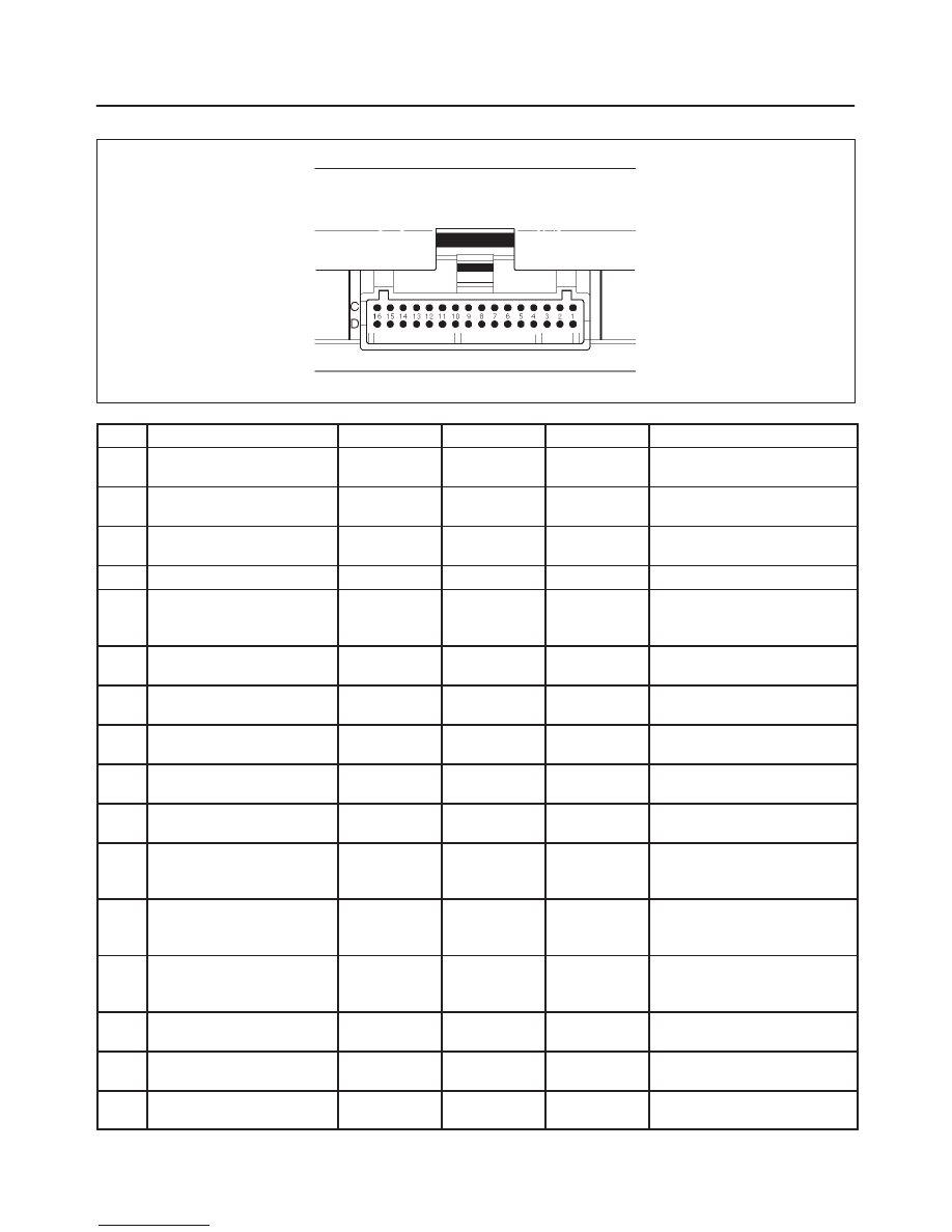
PCM Pinout Table, 32-Way White Connector – Row “D”
TS23345
PIN
PIN Function
Wire Color
IGN ON
ENG RUN
Refer To
D1
Injector Cylinder #2
GRN/ORN
B+
B+
General Description and
Operation, Fuel Injector
D2
Torque Converter Clutch
(TCC)
RED/YEL
0.0 V
0.0 V
On-Vehicle Service, Torque
Converter Clutch
D3
Injector Cylinder #1
GRN/WHT
B+
B+
General Description and
Operation, Fuel Injector
D4
Serial Data (8192)
RED
5.0 V
5.0 V
Chassis Electrical
D5
Ignition Control, Cylinder
#5
RED/YEL
0.0 V
0.1 V
General Description and
Operation, Ignition Control
Module
D6
Ignition Control, Cylinder
#3
RED/BLU
0.0 V
0.1 V
General Description and
Operation
D7
Speedometer
BLU/BLK
0.0 V
0.1 V
(at rest)
Chassis Electrical
D8
Sensor Ground 5V
Reference A Return
GRN
0.0 V
0.0 V
Appropriate Sensor
D9
Sensor Ground 5 V
Reference B Return
GRN
0.0 V
0.0 V
Appropriate Sensor
D10
Mass Air Flow (MAF)
YEL
4.9 V
4.2 V
General Description, Mass
Air Flow Sensor
D11
Camshaft Position Sensor
BLU
5.0 V
4.6 V
General Description and
Operation, Camshaft
Position Sensor
D12
Bank 1 HO2S 2 Low
BLU
0.0 V
0.1 V
General Description and
Operation, Catalyst Monitor
HO2S 2
D13
Bank 1 HO2S 2 High
GRN
0.3 V
0.6 V
General Description and
Operation, Catalyst Monitor
HO2S 2
D14
Bank 1 HO2S 1 Low
BLU
0.0 V
0.1 V
General Description and
Operation, Fuel HO2S 1
D15
Bank 1 HO2S 1 High
PNK
0.3 V
0.0-0.8 V
General Description and
Operation, Fuel HO2S 1
D16
Bank 2 HO2S 2 Low
WHT/BLU
0.0 V
0.1 V
General Description and
Operation, Catalyst HO2S 2
Нет комментариевНе стесняйтесь поделиться с нами вашим ценным мнением.
Текст