Isuzu Rodeo UE. Manual — part 342

6E2–123
RODEO 6VD1 3.2L ENGINE DRIVEABILITY AND EMISSIONS
about 3-6 g/second at idle to 100 g/second or greater
at the time of the 1-2 shift. If not, check for a restriction.
If DTC P0102 cannot be duplicated, the information
included in the Failure Records data can be useful in
determining vehicle mileage since the DTC was last set.
Test Description
Number(s) below refer to the step number(s) on the
Diagnostic Chart.
2. This step verifies that the problem is present at idle.
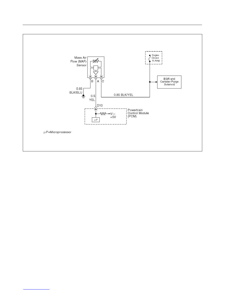
4. A voltage reading of less than 4 or over 5 volts at the
MAF sensor signal circuit indicates a fault in the
wiring or a poor connection.
5. This verifies that ignition feed voltage and a good
ground are available at the MAF sensor.
DTC P0102 – MAF Sensor Circuit Low Frequency
Step
Action
Value(s)
Yes
No
1
Was the “On-Board Diagnostic (OBD) System Check”
performed?
—
Go to
Step 2
Go to
OBD
System
Check
2
1. Start the engine.
2. With the engine idling, monitor “MAF Frequency”
display on the Tech 2.
Is the “MAF Frequency” below the specified value?
2.85 – 6.65
g/s
Go to
Step 4
Go to
Step 5
3
1. Ignition “ON,” engine “OFF.”
2. Review and record Tech 2 Failure Records data.
3. Operate the vehicle within Failure Records
conditions as noted.
4. Using a Tech 2, monitor “DTC” info for DTC P0102.
Does the Tech 2 indicate DTC P0102 failed this
ignition?
—
Go to
Step 4
Refer to
Diagnostic
Aids
4
1. Ignition “OFF.”
2. Disconnect the MAF sensor connector.
3. Ignition “ON,” engine “OFF.”
4. Using a DVM, measure voltage between the MAF
sensor signal circuit and battery ground.
Is the voltage near the specified value?
5 V
Go to
Step 5
Go to
Step 8
5
Connect a test light between the MAF sensor ignition
feed and ground circuits at the MAF sensor harness
connector.
Is the test light “ON?”
—
Go to
Step 13
Go to
Step 6
6
Connect a test light between the MAF sensor ignition
feed circuit and battery ground.
Is the test light “ON?”
—
Go to
Step 12
Go to
Step 7
7
1. Check for a poor connection at the MAF sensor.
2. If a poor connection is found, replace the faulty
terminal(s).
Was a poor connection found?
—
Verify repair
Go to
Step 11
8
1. Ignition “OFF.”
2. Disconnect the MAF sensor.
3. Disconnect the PCM connector for the MAF signal
circuit.
4. Ignition “ON,” engine “OFF.”
5. With the DVM, measure the voltage between the
MAF signal terminal at the PCM and battery ground.
Is the voltage under the specified value?
4 V
Go to
Step 9
Go to
Step 10

6E2–124
RODEO 6VD1 3.2L ENGINE DRIVEABILITY AND EMISSIONS
DTC P0102 – MAF Sensor Circuit Low Frequency
(Cont'd)
Step
No
Yes
Value(s)
Action
9
1. Ignition “OFF.”
2. Disconnect the PCM white connector.
3. Ignition “ON.”
4. Check the MAF sensor signal circuit for a short to 5
volts.
Is the action complete?
—
Verify repair
—
10
1. Ignition “OFF.”
2. Disconnect the PCM white connector.
3. Ignition “ON.”
4. Check the MAF sensor signal circuit between the
PCM and the MAF sensor for an open, short to
ground, or short to the MAF ground circuit.
Is the action complete?
—
Verify repair
Go to
Step 13
11
Locate and repair the open in the ground circuit to the
MAF sensor.
Is the action complete?
—
Verify repair
—
12
Locate and repair the open in the ignition feed circuit to
the MAF sensor.
Is the action complete?
—
Verify repair
—
13
Replace the MAF sensor.
Is the action complete?
—
Verify repair
Go to
Step 14
14
Replace the PCM.
IMPORTANT: The replacement PCM must be
programmed. Refer to
On-Vehicle Service in
Powertrain Control Module and Sensors for
procedures.
And also refer to latest service bulletin.
Check to see if the Latest software is released or not.
And then Down Load the LATEST PROGRAMMED
SOFTWARE to the replacement PCM.
Is the action complete?
—
Verify repair
—
6E2–125
RODEO 6VD1 3.2L ENGINE DRIVEABILITY AND EMISSIONS
Diagnostic Trouble Code (DTC) P0103 MAF Sensor Circuit High Frequency
D06RW057
Circuit Description
The mass air flow (MAF) sensor measures the amount of
air which passes through it into the engine during a given
time. The powertrain control module (PCM) uses the
mass air flow information to monitor engine operating
conditions for fuel delivery calculations. A large quantity
of air entering the engine indicates an acceleration or high
load situation, while a small quantity of air indicates
deceleration or idle.
The MAF sensor produces a frequency signal which can
be monitored using a Tech 2. The frequency will vary
within a range of around 4 to 7 g/s at idle to around 9000
Hz at maximum engine load. DTC P0103 will be set if the
signal from the MAF sensor is above the possible range of
a normally operating MAF sensor.
Conditions for Setting the DTC
f
The engine is running above 500 RPM for more than
10 seconds.
f
System voltage is above 11.5 volts.
f
MAF signal frequency is above 40 g/s for a total of 50
percent of the last 200 samples monitored. A sample
is taken every cylinder event.
Action Taken When the DTC Sets
f
The PCM will illuminate the malfunction indicator lamp
(MIL) the first time the fault is detected.
f
The PCM calculates an airflow value based on idle air
control valve position, throttle position, RPM and
barometric pressure.
f
The PCM will store conditions which were present
when the DTC was set as Freeze Frame and in the
Failure Records data.
Conditions for clearing the MIL/DTC
f
The PCM will turn the MIL “OFF” on the third
consecutive trip cycle during which the diagnostic has
been run and the fault condition is no longer present.
f
A history DTC P0103 will clear after 40 consecutive
warm-up cycles have occurred without a fault.
f
DTC P0103 can be cleared by using the Tech 2 “Clear
Info” function or by disconnecting the PCM battery
feed.
Diagnostic Aids
If DTC P0103 cannot be duplicated, the information
included in the Failure Records data can be useful in
determining vehicle mileage since the DTC was last set.
Test Description
Number(s) below refer to the step number(s) on the
Diagnostic Chart.
2. This step verifies that the problem is present at idle.
6E2–126
RODEO 6VD1 3.2L ENGINE DRIVEABILITY AND EMISSIONS
4. A frequency reading with the MAF sensor connector
disconnected indicates an electromagnetic
interference (EMI) related fault.
9. This vehicle is equipped with a PCM which utilizes
an electrically erasable programmable read only
memory (EEPROM). When the PCM is being
replaced, the new PCM must be programmed.
Refer to
PCM Replacement and Programming
Procedures in Powertrain Control Module (PCM)
and Sensor.
Нет комментариевНе стесняйтесь поделиться с нами вашим ценным мнением.
Текст