Isuzu Rodeo UE. Manual — part 519
7B–108 MANUAL TRANSMISSION
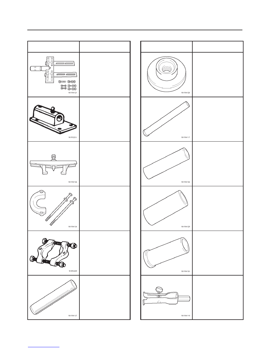
Special Tools (TREMEC T5R)
ILLUSTRATION
TOOL NO.
TOOL NAME
J–36842
Holding fixture;
Transmission
J–3289–20
Base; Holding fixture
J–8433
Gear puller
J–38878
Puller; Speed drive gear
J–22912–01
Puller plate
J–6133–01
Installer; Bearing & gear
ILLUSTRATION
TOOL NO.
TOOL NAME
J–37357
Installer; Counter shaft
bearing
J–25234
Installer; 5th driven gear
J–5590
Mainshaft support
J–37360
Spiral snap ring installer
J–37372
Synchronizer & gear
installer
J–29369–2
Remover; Input seal &
slip yoke seal
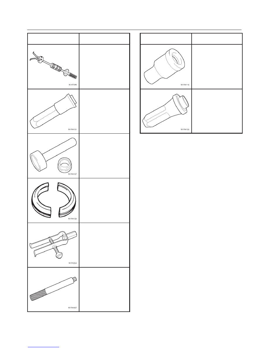
MANUAL TRANSMISSION 7B–109
ILLUSTRATION
TOOL NO.
TOOL NAME
J–23907
Slide hammer
J–37375
Installer; Input bearing
retainer seal
J–37358
Bearing race receiver &
case support
J–37359
Counter shaft front
bearing remover
J–26941
Remover; extension
housing oil seal
J–8092
Driver handle
ILLUSTRATION
TOOL NO.
TOOL NAME
J–23062–14
Remover & installer;
extension housing
bushing
J–38763
Installer; extension
housing oil seal
CLUTCH
7C–1
RODEO
TRANSMISSION
CLUTCH
CONTENTS
Service Precaution
7C–1
. . . . . . . . . . . . . . . . . . . . . .
General Description
7C–2
. . . . . . . . . . . . . . . . . . . . .
Diagnosis
7C–8
. . . . . . . . . . . . . . . . . . . . . . . . . . . . . .
Clutch Assembly
(X22SE, TREMEC T5R / MUA)
7C–9
. . . . . . . . . . .
Clutch Assembly (X22SE, TREMEC T5R)
and Associated Parts
7C–9
. . . . . . . . . . . . . . . . . .
Clutch Assembly (X22SE, MUA) and
Associated Parts
7C–10
. . . . . . . . . . . . . . . . . . . . . .
Removal
7C–10
. . . . . . . . . . . . . . . . . . . . . . . . . . . . .
Inspection and Repair
7C–11
. . . . . . . . . . . . . . . . . .
Installation
7C–15
. . . . . . . . . . . . . . . . . . . . . . . . . . . .
Clutch Assembly (6VD1, MUA)
7C–18
. . . . . . . . . . . .
Clutch Assembly (6VD1, MUA) and
Associated Parts
7C–18
. . . . . . . . . . . . . . . . . . . . . .
Removal
7C–18
. . . . . . . . . . . . . . . . . . . . . . . . . . . . .
Inspection and Repair
7C–20
. . . . . . . . . . . . . . . . . .
Installation
7C–24
. . . . . . . . . . . . . . . . . . . . . . . . . . . .
Clutch Control
7C–26
. . . . . . . . . . . . . . . . . . . . . . . . . .
Parts Location View
7C–26
. . . . . . . . . . . . . . . . . . . .
Removal
7C–27
. . . . . . . . . . . . . . . . . . . . . . . . . . . . .
Inspection and Repair
7C–27
. . . . . . . . . . . . . . . . . .
Installation
7C–28
. . . . . . . . . . . . . . . . . . . . . . . . . . . .
Master Cylinder
7C–30
. . . . . . . . . . . . . . . . . . . . . . . . .
Slave Cylinder
7C–31
. . . . . . . . . . . . . . . . . . . . . . . . . .
Disassembled View
7C–31
. . . . . . . . . . . . . . . . . . . .
Disassembly
7C–31
. . . . . . . . . . . . . . . . . . . . . . . . . .
Inspection and Repair
7C–31
. . . . . . . . . . . . . . . . . .
Reassembly
7C–32
. . . . . . . . . . . . . . . . . . . . . . . . . .
Main Data and Specifications
7C–33
. . . . . . . . . . . . .
Special Tools
7C–36
. . . . . . . . . . . . . . . . . . . . . . . . . . .
Service Precaution
WARNING: THIS VEHICLE HAS A SUPPLEMENTAL
RESTRAINT SYSTEM (SRS). REFER TO THE SRS
COMPONENT AND WIRING LOCATION VIEW IN
ORDER TO DETERMINE WHETHER YOU ARE
PERFORMING SERVICE ON OR NEAR THE SRS
COMPONENTS OR THE SRS WIRING. WHEN YOU
ARE PERFORMING SERVICE ON OR NEAR THE SRS
COMPONENTS OR THE SRS WIRING, REFER TO
THE SRS SERVICE INFORMATION. FAILURE TO
FOLLOW WARNINGS COULD RESULT IN POSSIBLE
AIR BAG DEPLOYMENT, PERSONAL INJURY, OR
OTHERWISE UNNEEDED SRS SYSTEM REPAIRS.
CAUTION: Always use the correct fastener in the
proper location. When you replace a fastener, use
ONLY the exact part number for that application.
ISUZU will call out those fasteners that require a
replacement after removal. ISUZU will also call out
the fasteners that require thread lockers or thread
sealant. UNLESS OTHERWISE SPECIFIED, do not
use supplemental coatings (Paints, greases, or other
corrosion inhibitors) on threaded fasteners or
fastener joint interfaces. Generally, such coatings
adversely affect the fastener torque and the joint
clamping force, and may damage the fastener. When
you install fasteners, use the correct tightening
sequence and specifications. Following these
instructions can help you avoid damage to parts and
systems.
7C–2
CLUTCH
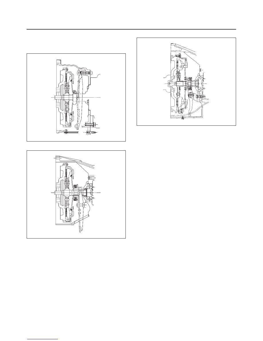
General Description
Clutch
X22SE, TREMEC T5R
A07RW034
X22SE, MUA
A07RW035
6VD1, MUA
A07RW031
The clutch assembly consists of the pressure plate
assembly and the driven plate assembly.
The clutch pedal is connected to the release bearing
through the shift fork.
The driven plate assembly is installed between the
flywheel and the pressure plate. Diaphragm spring
pressure holds the driven plate against the flywheel and
the pressure plate to provide the friction necessary to
engage the clutch.
Depressing the clutch pedal moves the shift fork against
the release bearing. The release bearing force
overcomes the force of the diaphragm spring and
separates the driven plate from the flywheel and pressure
plate to disengage the clutch.
For 6VD1 (3.2L) engine model, the pull–type clutch is
employed.
Нет комментариевНе стесняйтесь поделиться с нами вашим ценным мнением.
Текст