Isuzu Rodeo UE. Manual — part 621
8F–57
BODY STRUCTURE
601RW005
690RW006
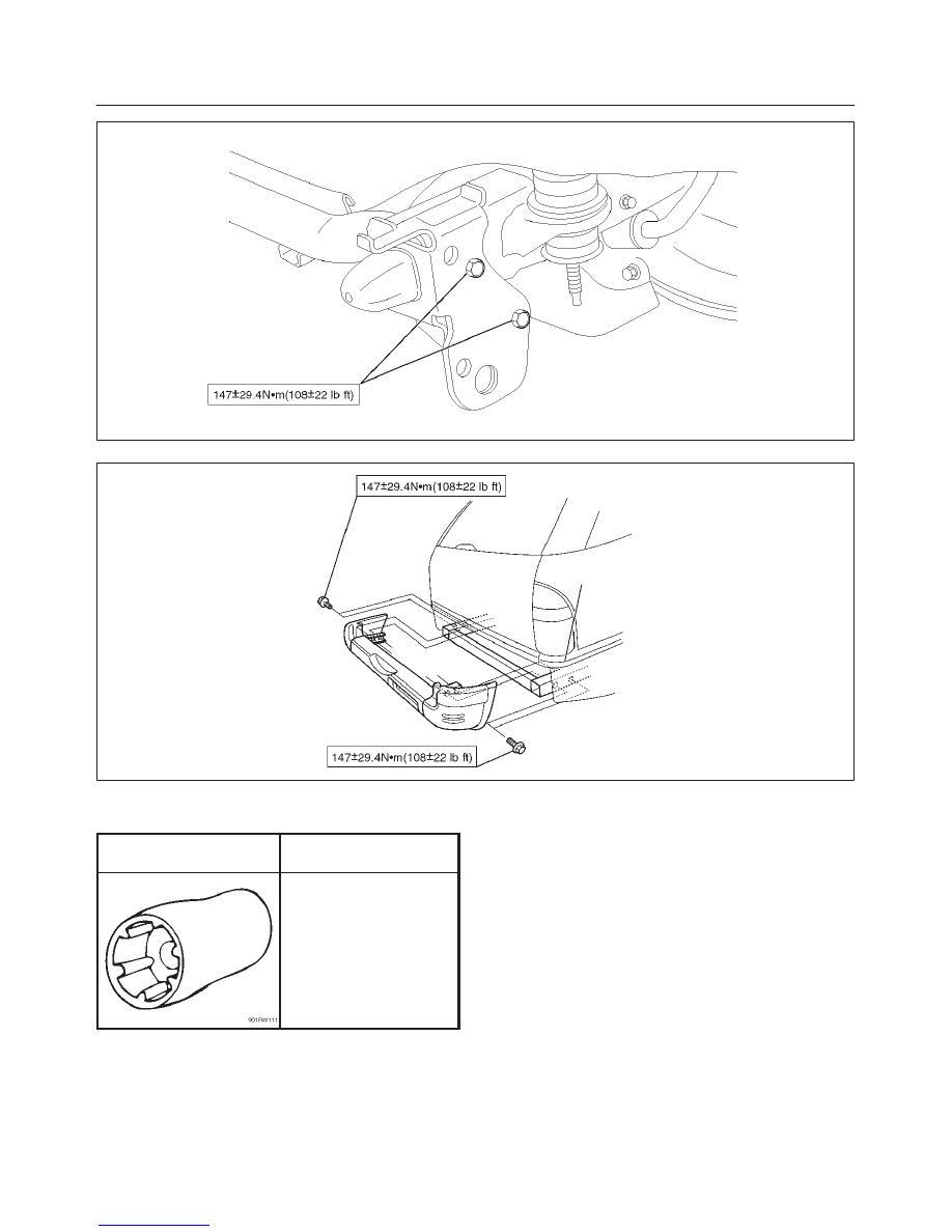
Special Tools
ILLUSTRATION
TOOL NO.
TOOL NAME
J–34355
Spare Tire Carrier Nut
Wrench
SEATS
8G–1
RODEO
BODY AND ACCESSORIES
SEATS
CONTENTS
Service Precaution
8G–1
. . . . . . . . . . . . . . . . . . . . . .
Front Seat Assembly
8G–2
. . . . . . . . . . . . . . . . . . . .
Front Seat Assembly and Associated Parts
8G–2
Removal
8G–2
. . . . . . . . . . . . . . . . . . . . . . . . . . . . .
Installation
8G–2
. . . . . . . . . . . . . . . . . . . . . . . . . . . .
Rear Seat Assembly
8G–3
. . . . . . . . . . . . . . . . . . . . .
Rear Seat Assembly and Associated Parts
8G–3
Removal
8G–3
. . . . . . . . . . . . . . . . . . . . . . . . . . . . .
Installation
8G–3
. . . . . . . . . . . . . . . . . . . . . . . . . . . .
Main Data and Specifications
8G–4
. . . . . . . . . . . . .
Service Precaution
WARNING: THIS VEHICLE HAS A SUPPLEMENTAL
RESTRAINT SYSTEM (SRS). REFER TO THE SRS
COMPONENT AND WIRING LOCATION VIEW IN
ORDER TO DETERMINE WHETHER YOU ARE
PERFORMING SERVICE ON OR NEAR THE SRS
COMPONENTS OR THE SRS WIRING. WHEN YOU
ARE PERFORMING SERVICE ON OR NEAR THE SRS
COMPONENTS OR THE SRS WIRING, REFER TO
THE SRS SERVICE INFORMATION. FAILURE TO
FOLLOW WARNINGS COULD RESULT IN POSSIBLE
AIR BAG DEPLOYMENT, PERSONAL INJURY, OR
OTHERWISE UNNEEDED SRS SYSTEM REPAIRS.
CAUTION: Always use the correct fastener in the
proper location. When you replace a fastener, use
ONLY the exact part number for that application.
ISUZU will call out those fasteners that require a
replacement after removal. ISUZU will also call out
the fasteners that require thread lockers or thread
sealant. UNLESS OTHERWISE SPECIFIED, do not
use supplemental coatings (Paints, greases, or other
corrosion inhibitors) on threaded fasteners or
fastener joint interfaces. Generally, such coatings
adversely affect the fastener torque and the joint
clamping force, and may damage the fastener. When
you install fasteners, use the correct tightening
sequence and specifications. Following these
instructions can help you avoid damage to parts and
systems.
8G–2
SEATS
Front Seat Assembly
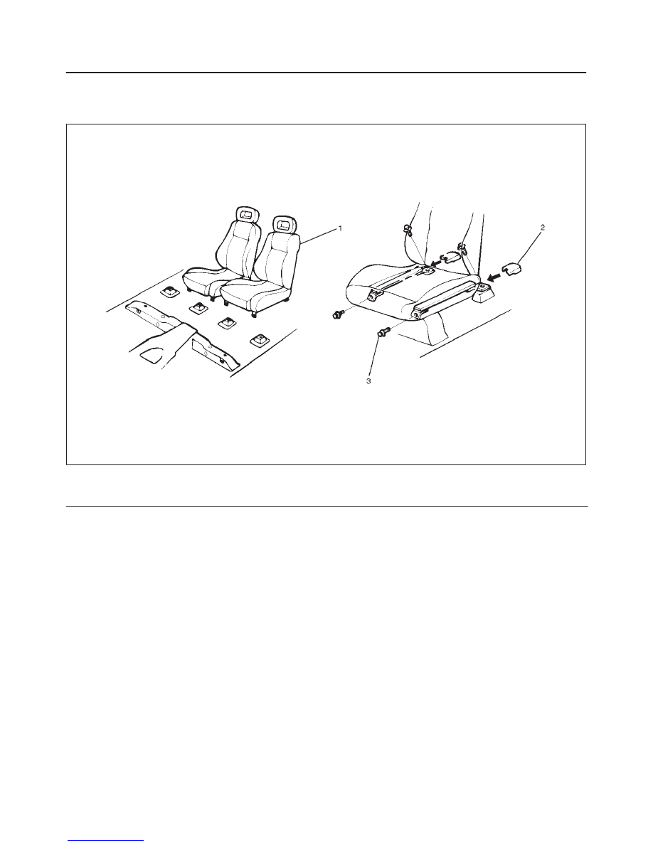
Front Seat Assembly and Associated Parts
750RW013
Legend
(1) Seat Assembly
(2) Adjuster Cover
(3) Bolt
Removal
1. Disconnect the battery ground cable.
2. Remove the adjuster cover.
3. Remove the bolt.
4. Remove the front seat assembly.
Installation
To install, follow the removal steps in the reverse order,
noting the following points:
1. Tighten the front seat assembly fixing bolts to the
specified torque.
Torque: 39 N·m (29 lb ft)
SEATS
8G–3
Rear Seat Assembly
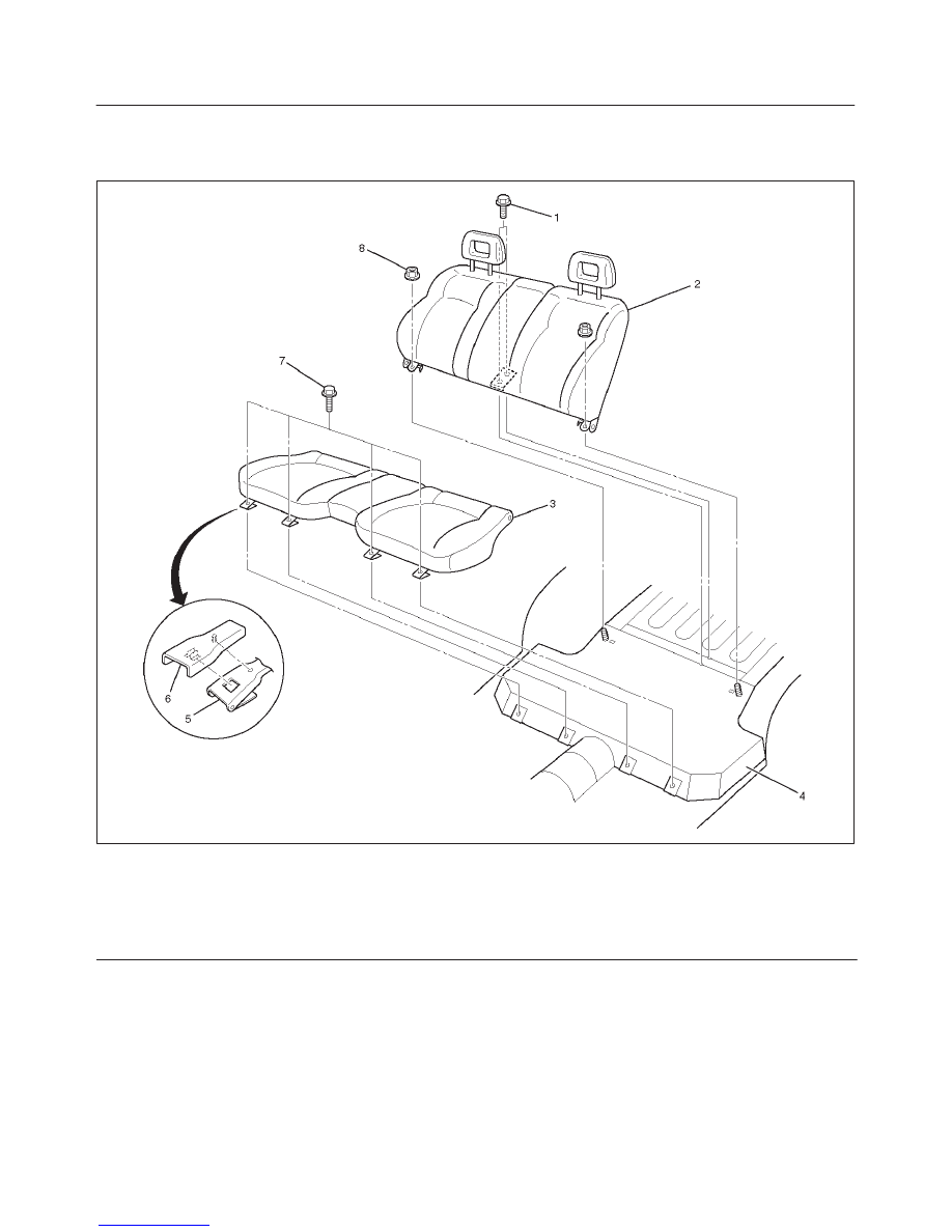
Rear Seat Assembly and Associated Parts
755RW022
Legend
(1) Bolt; Seatback
(2) Rear Seatback Assembly
(3) Rear Seat Cushion Assembly
(4) Body Floor Panel
(5) Bracket; Seat Cushion To Body
(6) Rear Seat Cushion Cover
(7) Bolt; Seat Cushion
(8) Nut; Seatback
Removal
1. Remove the rear seat cushion cover.
2. Remove the seat cushion fixing bolt.
3. Remove the rear seat cushion assembly.
4. Remove the seatback fixing nut.
5. Remove the seatback fixing bolt.
6. Remove the rear seat assembly.
Installation
To install, follow the removal steps in the reverse order,
noting the following point:
1. Tighten the rear seat fixing bolts to the specified
torque.
Torque: 39 N·m (29 lb ft)
Нет комментариевНе стесняйтесь поделиться с нами вашим ценным мнением.
Текст