Isuzu Rodeo UE. Manual — part 148
ENGINE COOLING (X22SE 2.2L)
6B–8
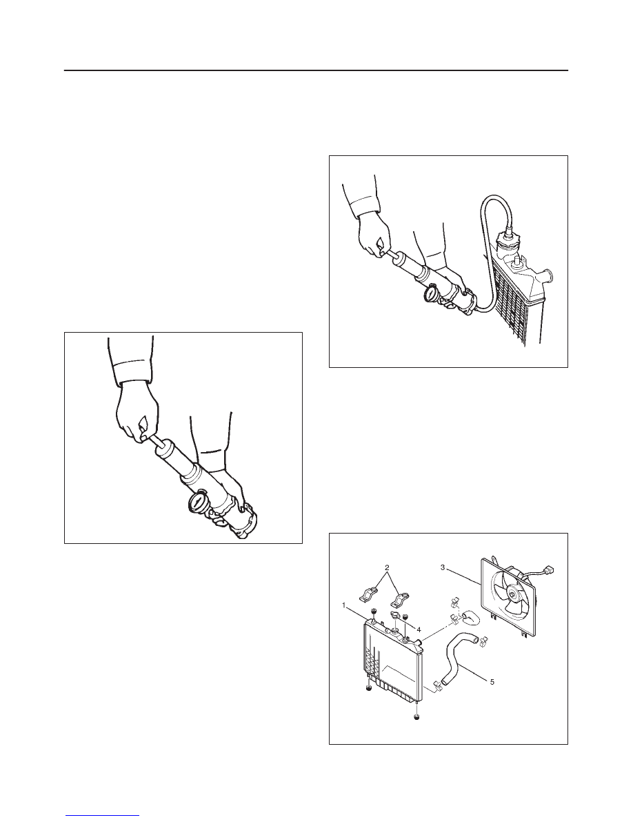
8. Lift out the radiator assembly with hose, taking care
not to damage the radiator core with fan blade.
9. Remove rubber cushions on both sides at the bottom.
Inspection
Radiator Cap
Measure the valve opening pressure of the pressurizing
valve with a radiator filler cap tester.
Replace the cap if the valve opening pressure is outside
the standard range.
Valve opening pressure kPa (psi) 93.3
∼
122.7
(13.5
∼
17.8)
Cap tester: J–24460–01
Adapter: J–33984–A
Check the condition of the vacuum valve in the center of
the valve seat side of the cap. If considerable rust or dirt is
found, or if the valve seat cannot be moved by hand, clean
or replace the cap.
Valve opening vacuum kPa (psi) 1.96
∼
4.91
(0.28
∼
0.71)
110RS006
Radiator Core
1. A bent fin may result in reduced ventilation and
overheating may occur. All bent fins must be
straightened. Pay close attention to the base of the fin
when it is being straightened.
2. Remove all dust, bugs and other foreign material.
Flushing the Radiator
Thoroughly wash the inside of the radiator and the engine
coolant passages with cold water and mild detergent.
Remove all sign of scale and rust.
Cooling System Leakage Check
Use a radiator cap tester to force air into the radiator
through the filler neck at the specified pressure of 196 kPa
(28.5 psi) with a cap tester:
f
Leakage from the radiator
f
Leakage from the coolant pump
f
Leakage from the water hoses
f
Check the rubber hoses for swelling.
Cap tester: J–24460–01
Adapter: J–33984–A
110RX002
Installation
1. Install rubber cushions on both sides of radiator
bottom.
2. Install radiator assembly with hose, taking care not to
damage the radiator core with a fan blade.
3. Install bracket and support the radiator upper tank
with the bracket and secure the radiator.
4. Connect reserve tank hose.
5. Install lower fan guide (6).
6. Connect radiator inlet hose and outlet hose to the
engine.
110RX003
6B–9
ENGINE COOLING (X22SE 2.2L)
7. Connect battery ground cable.
8. Pour engine coolant up to filler neck of radiator, and
up to MAX mark of reserve tank.
Important operation (in case of 100% engine coolant
change) procedure for filling with engine coolant.
D
Remove radiator cap.
D
Fill with engine coolant (EC) to the radiator filler
neck.
D
Fill with EC to the “MAX” line on the reservoir.
D
Start the engine with the radiator cap removed and
bring to operating temperature by running engine at
2,500
∼
3,000 rpm for 30 minutes.
D
By EC temperature gauge reading make sure that
the thermostat is open.
D
If air bubbles come up to the radiator filler neck,
replenish with EC. Repeat until the EC level does
not drop any further. Install the radiator cap and
stop the engine.
D
Replenish EC to the “MAX” line on the reservoir and
leave as it is until the engine gets cool.
D
After the engine gets cool, start the engine and
make sure there is no water running noise heard
from the heater core while the engine runs at 3000
rpm.
D
Should water running noise be heard, repeat the
same procedure from the beginning.
Main Data and Specifications
General Specifications
Cooling system
Engine Coolant forced circulation
Radiator
(1 tube in row) Tube type corrugated
Heat radiation capacity
54,000 kcal/h (62.8 kw)
Heat radiation area
7.677m
@
(0.878ft
@
)
Radiator front area
0.264m
@
(0.028ft
@
)
Radiator dry weight (with fan)
32N (7.2lb)
Radiator cap valve opening pressure
93.3
∼
122.7kpa (13.5
∼
17.8psi)
Engine coolant capacity
1.8lit (0.48 US gal)
Engine coolant pump
Centrifugal type
Thermostat
Bypass type
Engine coolant total capacity
7.2lit (1.9 US gal)
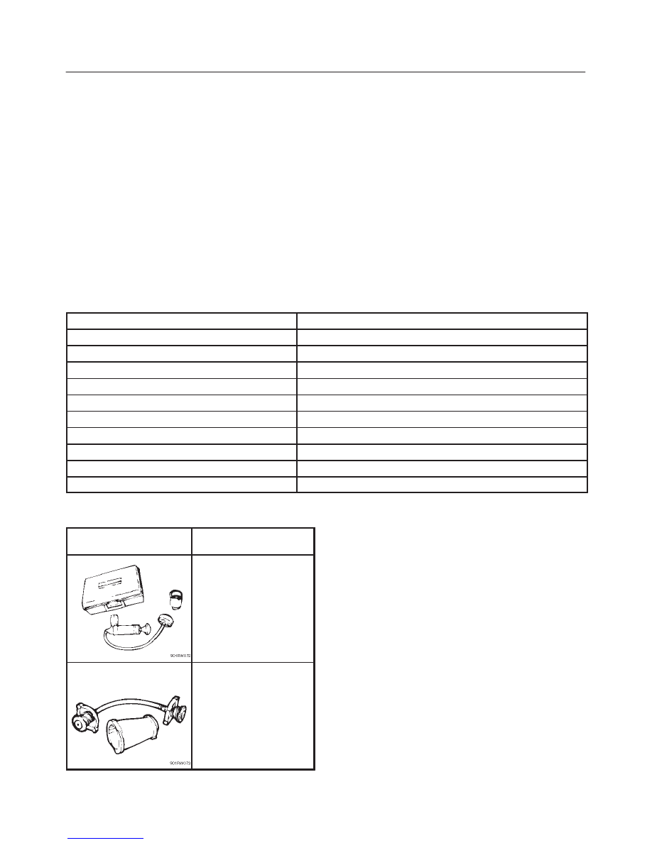
Special Tool
ILLUSTRATION
TOOL NO.
TOOL NAME
J–24460–01
Tester; radiator cap
J–33984–A
Adapter; radiator cap
6C–1
ENGINE FUEL (X22SE 2.2L)
RODEO
ENGINE
ENGINE FUEL (X22SE 2.2L)
CONTENTS
Service Precaution
6C–1
. . . . . . . . . . . . . . . . . . . . . .
General Description
6C–2
. . . . . . . . . . . . . . . . . . . . .
Fuel Metering
6C–3
. . . . . . . . . . . . . . . . . . . . . . . . . . .
Fuel Filter
6C–4
. . . . . . . . . . . . . . . . . . . . . . . . . . . . . .
Fuel Filter and Associated Parts
6C–4
. . . . . . . . .
Removal
6C–4
. . . . . . . . . . . . . . . . . . . . . . . . . . . . .
Inspection
6C–4
. . . . . . . . . . . . . . . . . . . . . . . . . . . .
Installation
6C–4
. . . . . . . . . . . . . . . . . . . . . . . . . . . .
Inspection
6C–4
. . . . . . . . . . . . . . . . . . . . . . . . . . . .
In–Tank Fuel Filter
6C–4
. . . . . . . . . . . . . . . . . . . . .
Fuel Pump Flow Test
6C–5
. . . . . . . . . . . . . . . . . . .
Fuel Pump
6C–6
. . . . . . . . . . . . . . . . . . . . . . . . . . . . .
Fuel Pump and Associated Parts
6C–6
. . . . . . . .
Removal
6C–6
. . . . . . . . . . . . . . . . . . . . . . . . . . . . .
Installation
6C–6
. . . . . . . . . . . . . . . . . . . . . . . . . . . .
Fuel Tube / Quick – Connector Fittings
6C–7
. . . . .
Precautions
6C–7
. . . . . . . . . . . . . . . . . . . . . . . . . . .
Cautions During Work
6C–7
. . . . . . . . . . . . . . . . . .
Removal
6C–7
. . . . . . . . . . . . . . . . . . . . . . . . . . . . .
Reuse of Quick–Connector
6C–9
. . . . . . . . . . . . .
Assembling Advice
6C–9
. . . . . . . . . . . . . . . . . . . .
Fuel Pump Relay
6C–10
. . . . . . . . . . . . . . . . . . . . . . . .
General Description
6C–10
. . . . . . . . . . . . . . . . . . . .
Fuel Tank
6C–10
. . . . . . . . . . . . . . . . . . . . . . . . . . . . . .
Fuel Tank and Associated Parts
6C–10
. . . . . . . . .
Removal
6C–11
. . . . . . . . . . . . . . . . . . . . . . . . . . . . .
Installation
6C–11
. . . . . . . . . . . . . . . . . . . . . . . . . . . .
Fuel Gage Unit
6C–11
. . . . . . . . . . . . . . . . . . . . . . . . . .
Removal and Installation
6C–11
. . . . . . . . . . . . . . .
Fuel Filler Cap
6C–12
. . . . . . . . . . . . . . . . . . . . . . . . . .
General Description
6C–12
. . . . . . . . . . . . . . . . . . . .
Inspection
6C–12
. . . . . . . . . . . . . . . . . . . . . . . . . . . .
Main Data and Specifications
6C–13
. . . . . . . . . . . . .
Special Tool
6C–13
. . . . . . . . . . . . . . . . . . . . . . . . . . . .
Service Precaution
WARNING: THIS VEHICLE HAS A SUPPLEMENTAL
RESTRAINT SYSTEM (SRS). REFER TO THE SRS
COMPONENT AND WIRING LOCATION VIEW IN
ORDER TO DETERMINE WHETHER YOU ARE
PERFORMING SERVICE ON OR NEAR THE SRS
COMPONENTS OR THE SRS WIRING. WHEN YOU
ARE PERFORMING SERVICE ON OR NEAR THE SRS
COMPONENTS OR THE SRS WIRING, REFER TO
THE SRS SERVICE INFORMATION. FAILURE TO
FOLLOW WARNINGS COULD RESULT IN POSSIBLE
AIR BAG DEPLOYMENT, PERSONAL INJURY, OR
OTHERWISE UNNEEDED SRS SYSTEM REPAIRS.
CAUTION: Always use the correct fastener in the
proper location. When you replace a fastener, use
ONLY the exact part number for that application.
ISUZU will call out those fasteners that require a
replacement after removal. ISUZU will also call out
the fasteners that require thread lockers or thread
sealant. UNLESS OTHERWISE SPECIFIED, do not
use supplemental coatings (Paints, greases, or other
corrosion inhibitors) on threaded fasteners or
fastener joint interfaces. Generally, such coatings
adversely affect the fastener torque and the joint
clamping force, and may damage the fastener. When
you install fasteners, use the correct tightening
sequence and specifications. Following these
instructions can help you avoid damage to parts and
systems.
6C–2
ENGINE FUEL (X22SE 2.2L)
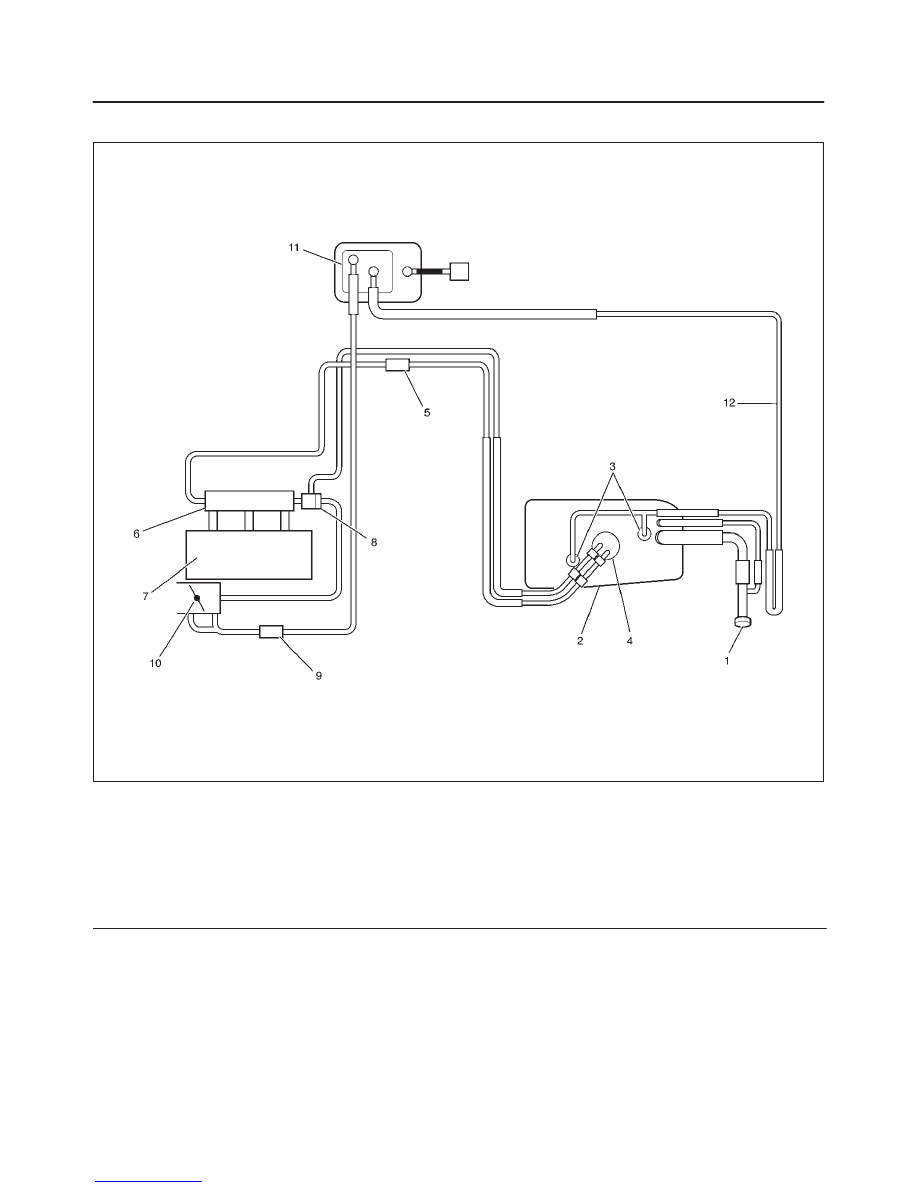
General Description
140RX008
Legend
(1) Fuel Filter Cap
(2) Fuel Tank
(3) Rollover Valve
(4) Fuel Pump and Sender Assembly
(5) Fuel Filter
(6) Fuel Rail
(7) Intake Manifold
(8) Fuel Pressure Control Valve
(9) Duty Solenoid Valve
(10) Throttle Valve
(11) Canister
(12) Evapo Pipe
Нет комментариевНе стесняйтесь поделиться с нами вашим ценным мнением.
Текст