Isuzu Rodeo UE. Manual — part 540
8D–8
WIRING SYSTEM
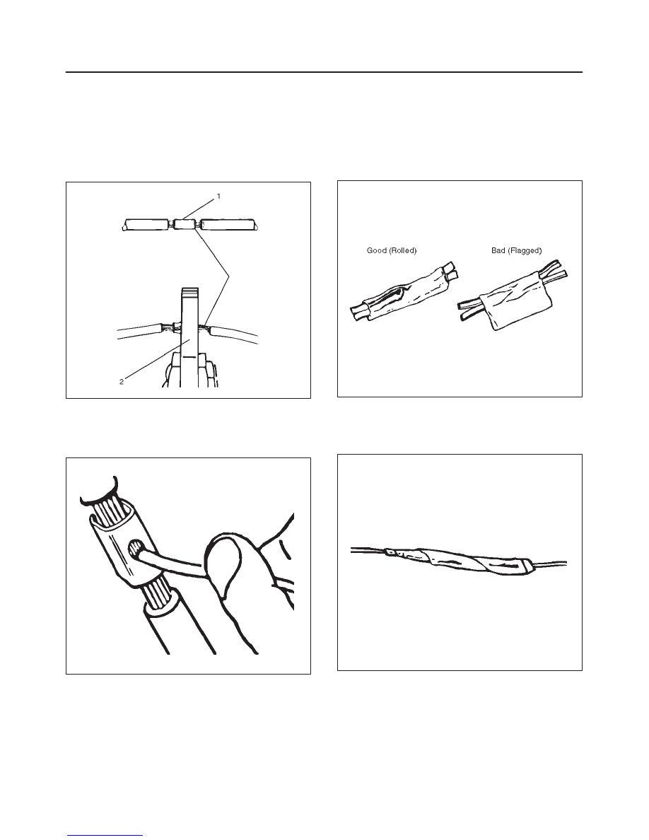
Before crimping the ends of the clip (1), be sure that:
f
The wires extend beyond the clip in each direction.
f
No strands of wire are cut loose, and
f
No insulation is caught under the clip.
Crimp the splice again, once on each end.
Does not let the crimping tool (2) extend beyond the edge
of the clip or you may damage or nick the wires as shown
in the figure.
D08RW145
5. Apply 60/40 resin core solder to the opening in the
back of the clip as shown in the figure.
Follow the manufacturer’s instructions for the solder
equipment you are using.
D08RW146
6. Center and roll the splicing tape.
The tape should cover the entire splice.
Roll on enough tape to duplicate the thickness of the
insulation on the existing wires.
Does not flag the tape. Flagged tape may not provide
enough insulation, and the flagged ends will tangle
with the other wires in the harness as shown in the
figure.
D08RW147
If the wire does not belong in a conduit or other
harness covering, tape the wire again. use a winding
motion to cover the first piece of tape as shown in the
figure.
D08RW148
8D–9
WIRING SYSTEM
Symbols and Abbreviations
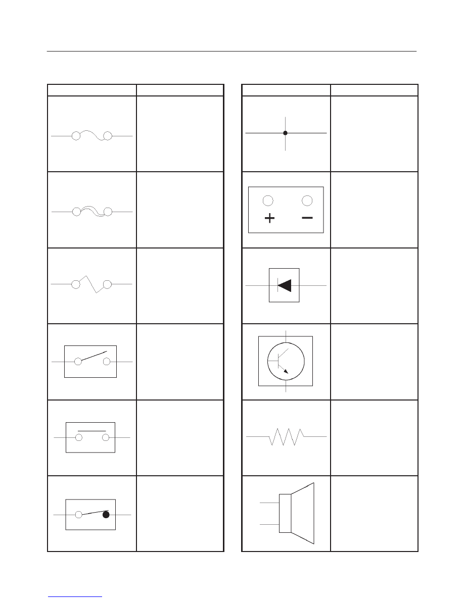
Symbols
Symbol
Meaning of Symbol
Fuse
Fusible link
Fusible link wire
Switch
Switch
Switch
(Normal close type)
Symbol
Meaning of Symbol
Contact wiring
Battery
Diode
Electronic parts
Resistor
Speaker
8D–10
WIRING SYSTEM
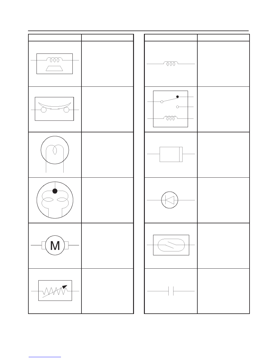
Symbol
Meaning of Symbol
Buzzer
Circuit breaker
Bulb
Double filament bulb
Motor
Variable register Rheo-
stat
Symbol
Meaning of Symbol
Coil (inductor), solenoid,
magnetic valve
Relay
Connector
Light emitting diode
Reed switch
Condenser
8D–11
WIRING SYSTEM
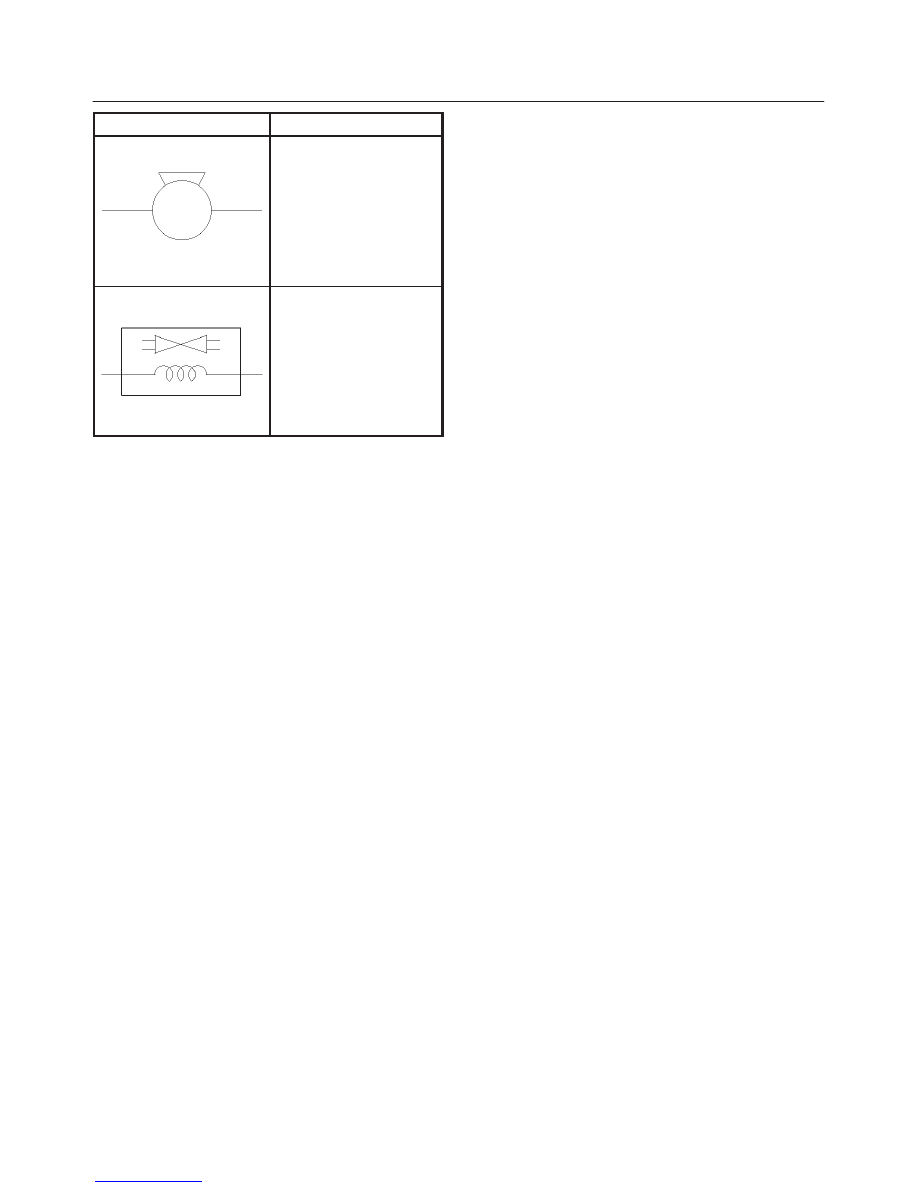
Symbol
Meaning of Symbol
Horn
Vacuum switching valve
Нет комментариевНе стесняйтесь поделиться с нами вашим ценным мнением.
Текст