Isuzu Rodeo UE. Manual — part 479

TRANSMISSION CONTROL SYSTEM (4L30–E)
7A1–35
Diagnostic Aids
f
Refer to the accompanying chart for the normal range
signals and the illegal combinations.
f
Inspect the wiring for poor electrical connections at
the PCM and at the transmission 8–way connector.
Look for possible bent, backed out, deformed or
damaged terminals. Check for weak terminal tension
as well. Also check for a chafed wire that could short
to bare metal or other wiring. Inspect for a broken wire
inside the insulation.
f
When diagnosing for a possible intermittent short or
open condition, move the wiring harness while
observing test equipment for a change.
f
Refer to the “Range Switch Logic Table” or
“Functional Test Procedure” for further information.
Test Description
The numbers below refer to the step numbers on the
diagnostic chart:
3. This test checks the indicated range signal to the
manual valve actually selected.
6. This test checks for continuity between each
selected range switch connector terminals.
Range Switch Logic Table
Range
Range Switch Pin
g
Position
A
B
C
P(G)
Park
ON
OFF
OFF
ON
Reverse
ON
ON
OFF
OFF
Neutral
OFF
ON
OFF
ON
D4
OFF
ON
ON
OFF
D3
ON
ON
ON
ON
2
ON
OFF
ON
OFF
L
OFF
OFF
ON
ON
Illegal
OFF
OFF
OFF
OFF
Illegal
OFF
OFF
OFF
ON

7A1–36 TRANSMISSION CONTROL SYSTEM (4L30–E)
DTC P0706 Transmission Range Switch (Mode Switch) Performance
Step
Action
Yes
No
1
Were you sent here from the “Powertrain On–Board Diagnostic
(OBD) System Check”?
Go to Step 2
Go to OBD
System Check
Refer to
Driveability and
Emissions in
Engine section
2
Perform the following checks:
f
The transmission linkage from the select lever to the manual
valve is adjusted properly.
f
Diagnostic circuit check.
Were the checks performed?
Go to Step 3
—
3
1. Install the scan tool.
2. With the engine “off”, turn the ignition switch “on”.
NOTE: Before clearing DTC(s), use the scan tool to record “Freeze
Frame” and “Failure Records” for reference, as data will be lost
when the “Clear Info” function is used.
3. Record the DTC “Freeze Frame” and “Failure Records”.
4. Select each transmission range: D1, D2, D3, D4, N, R, and P.
Does each selected transmission range match the scan tool
“Range Switch” display?
Go to Diagnostic
Aids
Go to Step 4
4
Are all range switch pin displays incorrect?
Go to Step 5
Go to Step 6
5
Check fuse and wiring to the 8–way connector terminal 5(D) for
opens.
Refer to Mode Switch in Automatic Transmission (4L30–E)
section.
If no problem was found, replace the range switch.
Is the replacement complete?
Go to Step 9
—
6
1. Disconnect the 8–way range switch connector.
2. Using ohmmeter, check continuity between terminal 5(D) and
respectively terminals 3(G), 6(C), 7(B) and 8(A) of the 8–way
range switch connector.
3. Move shift selector lever through all positions and compare
results with “Range Switch Logic Table”.
Is one range switch pin display incorrect?
Go to Step 7
Go to Step 8
7
Check the affected wiring and connector, and repair.
Is the repair complete?
Go to Step 9
—
8
Check the Powertrain Control Module (PCM) connectors for poor
connection.
If no problem was found, replace the PCM.
Is the replacement complete?
Go to Step 9
—
9
1. After the repair is complete, use the scan tool to select “DTC”,
then “Clear Info” function and road test the vehicle.
2. Review the scan tool “DTC Info”.
Has the last test failed or is the current DTC displayed?
Begin diagnosis
again
Go to Step 1
Repair verified
Exit DTC table
TRANSMISSION CONTROL SYSTEM (4L30–E)
7A1–37
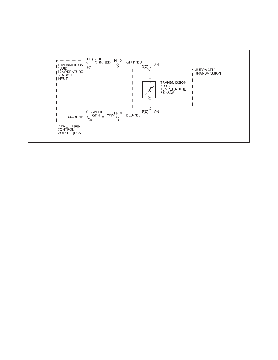
DTC P0711 Transmission Fluid Temperature (TFT) Sensor Circuit
Range/Performance
D07RW018
Circuit Description
The TFT sensor is a thermister that controls the signal
voltage to the PCM. The PCM supplies a 5 volt reference
signal to the sensor on circuit GRN/RED. When the
transmission fluid is cold, the sensor resistance is high
and the PCM detects high signal voltage. As the
transmission fluid temperature increases to normal
operating temperature of 100
°
C (212
°
F), the sensor
resistance becomes less and the voltage decreases to
1.5 to 2 volts.
When the PCM detects a TFT sensor that remains at the
startup value, or a sensor that has a change delta of
greater than 20
°
C (36
°
F) less than 1 second, DTC P0711
sets. DTC P0711 is a type D.
Conditions For Setting The DTC
f
No VSS DTCs P0722 or P0723.
f
No Transmission Component Slipping DTC P1870.
f
Engine running.
f
TFT is between 20 A/D (Analog/Digital) counts and
248 A/D counts.
f
TFT is between –40
°
C (–40
°
F) and +21
°
C (69.8
°
F)
at engine startup.
f
Engine coolant temperature is greater than 70
°
C
(150
°
F).
f
Engine coolant temperature has changed by greater
than 50
°
C (90
°
F) since engine startup.
f
Vehicle speed has been greater than 5 mph for
greater than 410 seconds since engine startup
(cumulative timer).
f
TCC slip speed has been greater than 120 rpm for
greater than 410 seconds since engine startup
(cumulative timer).
f
Battery voltage is between 10 and 16 volts.
All of the above is true and either of the following occurs:
f
If the sensor is stuck, the TFT has not changed for
greater than 2 counts (from startup temperature) for
greater than 410 seconds.
f
If the sensor shows an unrealistic change, the TFT
exhibits a change delta of greater than 20
°
C (36
°
F),
greater than 14 times in 7 seconds.
Action Taken When The DTC Sets
f
Transmission default temperature will be:
80
°
C (176
°
F) if engine temperature code is set.
100
°
C (212
°
F) if engine temperature is warm.
80
°
C (176
°
F) if engine run time is greater than 5
minutes.
21
°
C (69.8
°
F) if engine run time is less than 5
minutes.
f
The PCM will not illuminate the Malfunction Indicator
Lamp (MIL).
Conditions For Clearing The DTC
f
The DTC can be cleared from the PCM history by
using a scan tool.
f
The DTC will be cleared from history when the vehicle
has achieved 40 warmup cycles without a failure
reported.
f
The PCM will cancel the DTC default actions when
the fault no longer exists and the ignition is cycled “off”
long enough to power down the PCM.
Diagnostic Aids
f
Inspect the wiring for poor electrical connection at the
PCM. Inspect the wiring for poor electrical
connections at the transmission 16–way connector
H–10. Look for the following conditions:
a. A bent terminal
b. A backed out terminal

7A1–38 TRANSMISSION CONTROL SYSTEM (4L30–E)
c. A damaged terminal
d. Poor terminal tension
e. A chafed wire
f. A broken wire inside the insulation
f
When diagnosing for an intermittent short or open
connection, move the wiring harness while watching
the test equipment for a change.
f
First diagnose and clear any engine DTCs or TP
Sensor codes. Then inspect for any transmission
DTCs that may have reset.
Test Description
The number below refers to the step number on the
diagnostic chart:
3. This test checks PCM and associated wiring up to
the 16–way connector H–10. If the voltage
increases to match chart the problem is isolated to
the transmission wiring.
Resistance Chart
°
C
°
F
Resistance (k
W
)
–40
–40
672
0
32
65
20
68
25
80
176
2.5
120
248
0.78
150
304
0.37
DTC P0711 Transmission Fluid Temperature (TFT) Sensor Circuit
Range/Performance
Step
Action
Yes
No
1
Was the Powertrain On–Board Diagnostic (OBD) System Check
performed?
Go to Step 2
Go to OBD
System Check
Refer to
Driveability and
Emissions in
Engine section
2
Perform the transmission fluid checking procedure. Refer to
Checking Transmission Fluid Level and Condition in Automatic
Transmission (4L30–E) section.
Did you perform the fluid checking procedure?
Go to Step 3
Go to Checking
Transmission
Fluid Level and
Condition in
Automatic
Transmission
(4L30–E) section
3
1. Install the scan tool.
2. With the engine “off”, turn the ignition switch to the “on”
position.
NOTE: Before clearing DTCs, use the scan tool in order to record
the Freeze Frame and Failure Records for reference. The Clear
Info function will erase the data.
3. Record the DTC Freeze Frame and Failure Records.
4. Select TFT on the scan tool.
5. While observing the scan tool display, move or massage the
engine wiring harness from PCM connectors F7 and D9 to the
transmission 16–way connector H–10.
Does the TFT change by more than
±
20
°
C (36
°
F)?
Go to Step 6
Go to Step 4
Нет комментариевНе стесняйтесь поделиться с нами вашим ценным мнением.
Текст