Isuzu Rodeo UE. Manual — part 643

9J1–9
RESTRAINT CONTROL SYSTEM
Chart B “AIR BAG” Warning Lamp Comes “ON” Steady
Step
Action
Yes
No
1
1. When measurements are requested in this chart use J–39200
DVM with correct terminal adapter from J–35616–A.
2. Ignition switch “OFF.”
3. Connect scan tool to data link connector, Follow directions as
given in the scan tool instruction manual.
4. Ignition switch “ON.”
5. Request SRS diagnostic trouble code display.
Does scan tool indicate “No Data Received”?
Go to Step 2
Go to Step 3
2
1. Ignition switch “OFF.”
2. Inspect SDM harness connector connection to SDM.
Is it securely connected to the SDM?
Ignition switch
“OFF.”
Replace SDM.
Go to Step 5
Connect SDM
securely to
de–activate
shorting clip in
SDM harness
connector.
Go to Step 5
3
Using scan tool, request SRS data list.
Is “ignition” more than 9 volts?
Go to Step 4
Ignition switch
“OFF.”
Replace SDM.
Go to Step 5
4
1. Ignition switch “OFF.”
2. Disconnect SRS coil and passenger air bag assemblies.
Yellow 2–pin connectors located at base of steering column
and behind the glove box assembly.
3. Disconnect SDM.
4. Measure resistance from SDM harness connector terminal “6”
to ground.
Does J–39200 display “0L” (infinite)?
Go to Chart A.
Replace SRS
harness.
Go to Step 5
5
Reconnect all SRS components, ensure all components are
properly mounted.
Was this step finished?
Repeat the “SRS
Diagnostic
System Check.”
Go to Step 5
RESTRAINT CONTROL SYSTEM
9J1–10
Chart C “AIR BAG” Warning Lamp Does Not Comes “ON” Steady
D09RW002
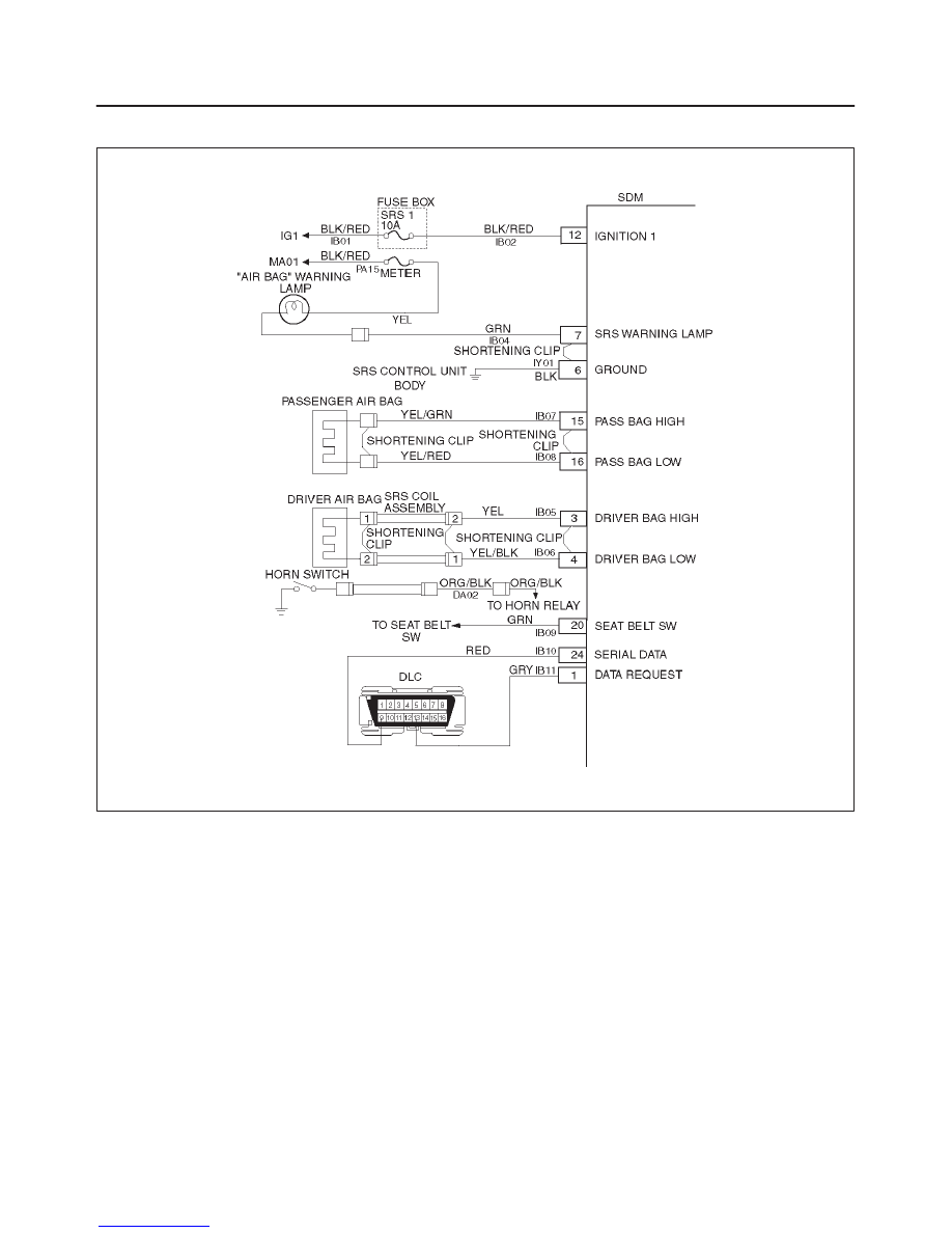
Circuit Description:
When the ignition switch is first turned “ON”, “ignition 1”
voltage is applied from the “MA01” meter fuse to the “AIR
BAG” warning lamp which is connected to “SRS warning
lamp”, terminal “7”. The “SRS–1” fuse apply system
voltage to the “ignition 1” inputs, terminals “12”. The SDM
responds by flashing the “AIR BAG” warning lamp seven
times. If “ignition 1” voltage is more than 16 volts, the
“AIR BAG” warning lamp will be still “OFF” solid with no
DTCs set.
Chart Test Description:
Number(s) below refer to step number(s) on the
diagnostic chart:
1. This test decides whether power is available to SDM
warning lamp power feed circuit.
2. This test determines whether the voltage is present
in the warning lamp circuit.
3. This test determines if the malfunction is in the
instrument cluster.
4. This test checks for open in the warning lamp
circuitry.
5. This test isolates the IB04–GRN circuit and checks
for a short in the IB04–GRN circuit to B+.
8. This test checks for a short from the SDM warning
lamp power feed circuit to ground.
9. This test determines whether the short to ground is
due to a short in the wiring.
9J1–11
RESTRAINT CONTROL SYSTEM
Chart C “AIR BAG” Warning Lamp Does Not Comes “ON” Steady
Step
Action
Yes
No
1
1. When measurements are requested in this chart use J–39200
DVM with correct terminal adapter from J–35616–A.
2. Ignition switch “OFF.”
3. Remove and inspect “MA01” meter fuse to the “AIR BAG”
warning lamp.
Is fuse good?
Go to Step 2
Go to Step 7
2
1. Ignition switch “OFF.”
2. Disconnect SRS coil and passenger air bag assemblies.
Yellow 2–pin connectors located at base of steering column
and behind the glove box assembly.
3. Disconnect SDM.
4. Ignition switch “ON.”
5. Measure voltage on SDM harness connector from terminal “7”
to terminal “6” (ground).
Is system voltage present on terminal “7”?
Go to Step 4
Go to Step 3
3
1. Ignition switch “OFF.”
2. Remove instrument meter cluster.
3. Check for proper connection to instrument cluster at
IB04–GRN terminal.
4. If OK, then remove and inspect “AIR BAG” bulb.
Is bulb good?
Go to Step 5
Replace bulb.
Go to Step 6
4
1. Ignition switch “OFF.”
2. Disconnect instrument meter cluster harness connector.
3. Ignition switch “ON.”
4. Measure voltage on SDM harness connector from terminal “7”
to terminal “6” (ground).
Is voltage 1 volt or less?
Go to Chart A.
Replace SRS
harness.
Go to Step 6
5
1. Install bulb.
2. Measure resistance from instrument meter cluster harness
connector IB04–GRN terminal to SDM harness connector
terminal “7”.
Is resistance 5.0 ohms or less?
Service
instrument meter
cluster.
Go to Step 6
Replace SRS
harness.
Go to Step 6
6
Reconnect all SRS components, ensure all components are
properly mounted.
Was this step finished?
Repeat the “SRS
Diagnostic
System Check.”
Go to Step 6
7
Were you sent here from chart C?
Go to Step 8
Go to Step 1
8
1. Replace “MA01” meter fuse.
2. Ignition switch “ON” wait 10 seconds then ignition switch
“OFF.”
3. Remove and inspect “MA01” meter fuse.
Is fuse good?
Install “MA01”
meter fuse.
Go to Step 10
Go to Step 9
RESTRAINT CONTROL SYSTEM
9J1–12
Chart C “AIR BAG” Warning Lamp Does Not Comes “ON” Steady (Cont’d)
Step
No
Yes
Action
9
1. Disconnect SRS coil and passenger air bag assemblies.
Yellow 2–pin connectors located at base of steering column
and behind the glove box assembly.
2. Disconnect SDM.
3. Replace “MA01” meter fuse.
4. Ignition switch “ON” wait to 10 seconds.
5. Ignition switch “OFF”.
6. Remove and inspection “MA01” meter fuse.
Is fuse good?
Install “MA01”
meter fuse.
Go to Chart A.
Replace SRS
harness.
Replace“MA01”
meter fuse.
Go to Step 10
10
Reconnect all SRS components, ensure all components are
properly mounted.
Was this step finished?
Repeat the “SRS
Diagnostic
System Check.”
Go to Step 10
Нет комментариевНе стесняйтесь поделиться с нами вашим ценным мнением.
Текст