Isuzu Rodeo UE. Manual — part 500

7B–32
MANUAL TRANSMISSION
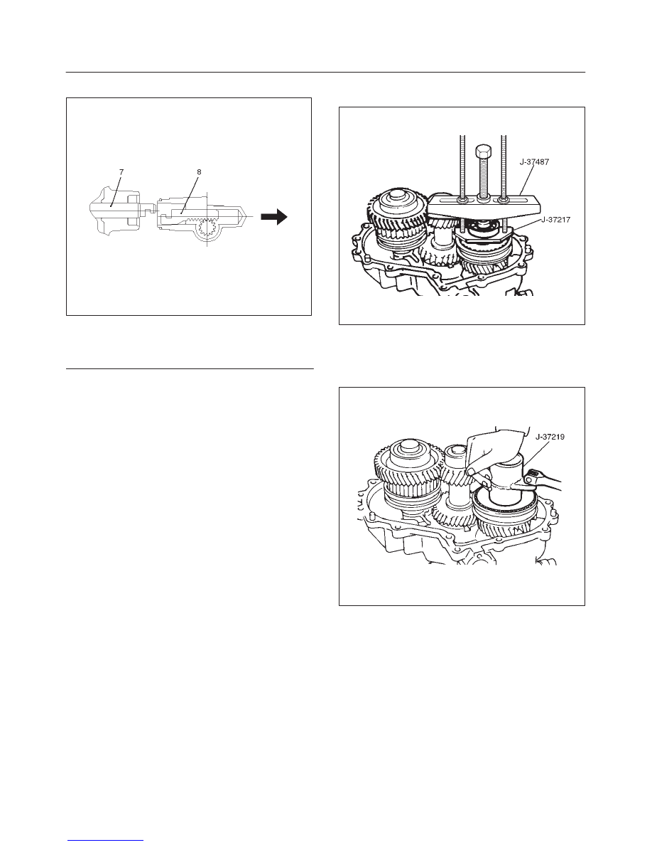
7. Remove the speedometer sensor(7).
Remove the plate(7).
Remove the driven gear bushing and driven gear(7).
NOTE: Apply a reference mark to the driven gear bushing
before removal.
8. Remove front companion flange(8) and rear
companion flange(9) using the flange holder
J–8614–11 to remove the end nut.
266RW001
9. Disconnect breather hose from transmission and
remove gear control box assembly(10).
10. Remove 2WD–4WD actuator assembly(11) by
performing the following steps:
1. Disconnect the actuator breather hose from
2WD–4WD actuator assembly(11).
220RW002
2. Remove the 2WD–4WD actuator assembly bolts.
3. Pull the 2WD–4WD actuator assembly with
2WD–4WD shift rod.
220RW027
Legend
(1) Shift Rod: 2WD–4WD (Position: 2WD)
(2) 2WD–4WD Actuator Assembly
(3) Pull
(4) Rear Case Assembly
(5) Position: 4WD
(6) Position: 2WD
4. Offset the actuator assembly.
220RW028
MANUAL TRANSMISSION
7B–33
5. Remove the actuator assembly.
220RW029
Legend
(7) Position: 4WD
(8) Mode: 2WD
NOTE: Before removing the transmission and transfer
assembly from vehicle, change the transfer mode to 2WD
using the 4WD push button switch on dash panel.
11. Remove the transfer rear cover assembly(12) from
the transfer case(28).
12. Regarding detent, shift arm, and interlock pin(13)
disassembly, refer to Detent, Shift Arm, and Interlock
Pin in Drive Line/Axle section.
13. Use a pair of snap ring pliers to remove the bearing
snap ring(14).
14. Use a bearing remover J–37217 and puller J–37487
to remove the ball bearing(15).
262RW032
15. Install the front companion flange temporarily.
Use the flange holder J–8614–11 and lock nut wrench
J–37219 to remove the lock nut(16).
Remove the front companion flange.
226RW137
7B–34
MANUAL TRANSMISSION
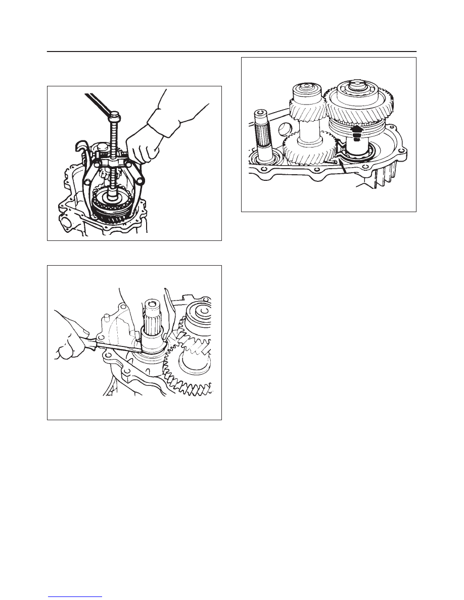
16. Remove high-low clutch sleeve(17).
Use the universal puller to remove the high-low clutch
hub(17) and transfer input gear(18).
226RS070
17. Remove needle bearing(19), bearing collar(20),
ball(21), and plate(22).
226RS071
18. Use a pair of snap ring pliers to remove the bearing
snap ring(23).
19. Use a plastic hammer to tap the front output gear
assembly(24) free.
262RS009
20. Remove bearing snap ring(25) by using a pair of snap
ring pliers.
21. Remove the counter gear assembly(26) from the
transfer case(28).
22. Remove 1–2 and 3–4 indicator switch, pin and
ball(27).
23. Remove the transfer case assembly(28) from the
transmission case.
f
Refer to Transfer Case Assembly in Drive Line/Axle
section for repair of transfer case assembly.
24. Pull out intermediate plate with gear assembly(29)
from transmission case.
Reassembly
1. Apply recommended liquid gasket (LOCTITE 17430)
or its equivalent to the transmission case(30),
intermediate plate(29) and transfer case(28) fitting
surfaces.
2. Install the intermediate plate with gear assembly(29)
to the transmission case(30).
Pull out the top gear shaft until the ball bearing snap
ring groove protrudes from the transmission case
front cover fitting face.
Avoid subjecting the mainshaft to sudden shock or
stress.
3. Install the transfer case assembly(28) to the
intermediate plate with gear assembly.
Tighten the eight transmission-transfer case bolts to
the specified torque.
Torque: 37 N·m (27 lb ft)
Refer to Transfer Rear Case Assembly in Drive
Line/Axle section for oil seal replacement.
4. Install 1–2 and 3–4 indicator switch, pin and ball(27).
5. Install the counter gear assembly(26) to the transfer
case(28).
6. Use a pair of snap ring pliers to install the snap
ring(25) to the transfer case(28).
MANUAL TRANSMISSION
7B–35
NOTE: The snap ring must be fully inserted into the
transfer case snap ring groove.
7. Install front output gear assembly(24).
8. Use a pair of snap ring pliers to install the snap ring
(23) to the transfer case(28).
NOTE: The snap ring must be fully inserted into the
transfer case snap ring groove.
9. Install plate(22), ball(21), bearing collar(20), needle
bearing(19), and transfer input gear(18).
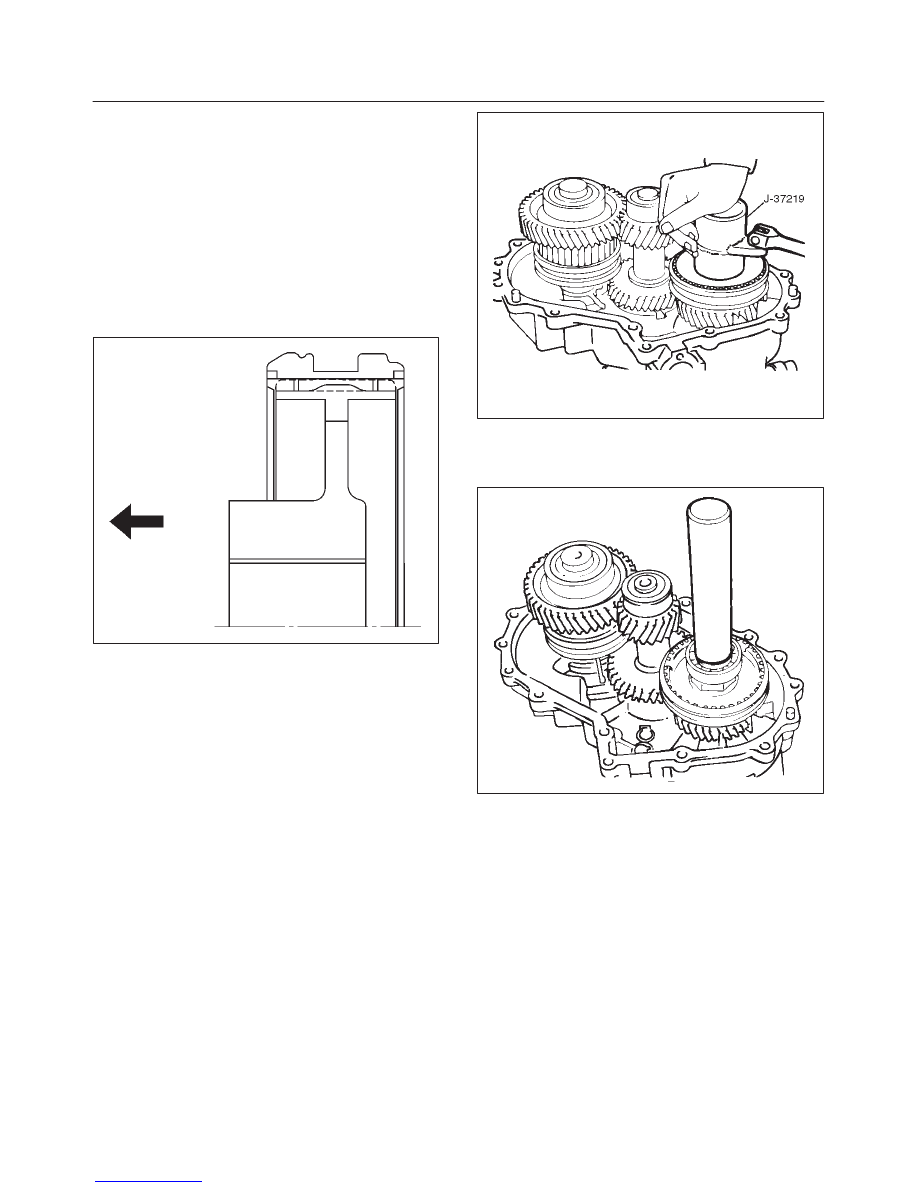
10. Install High-low clutch hub and sleeve(17).
The clutch hub face (with the heavy boss) must be
facing the transfer input gear side.
226RW152
11. Install the front companion flange temporarily.
f
Use the flange holder J–8614–11 and lock nut
wrench J–37219 to install the lock nut(16).
Torque: 137 N·m (101 lb ft)
226RS068
12. Use the punch to stake the lock nut at one spot.
13. Use a suitable drift and hammer to install the ball
bearing(15).
226RS079
14. Use a pair of snap ring pliers to install the bearing
snap ring(14).
15. Regarding detent, shift arm, and interlock pin(13)
assembly, refer to Detent, Shift Arm, and Interlock Pin
in Drive Line/Axle section.
Нет комментариевНе стесняйтесь поделиться с нами вашим ценным мнением.
Текст