Isuzu Rodeo UE. Manual — part 355

6E2–175
RODEO 6VD1 3.2L ENGINE DRIVEABILITY AND EMISSIONS
f
DTC P0135 can be cleared by using the Tech 2 “Clear
Info” function or by disconnecting the PCM battery
feed.
Diagnostic Aids
Check for the following conditions:
f
Poor connection at PCM – Inspect harness connectors
for backed-out terminals, improper mating, broken
locks, improperly formed or damaged terminals, and
poor terminal-to-wire connection.
f
Damaged harness – Inspect the wiring harness for
damage. If the harness appears to be OK, observe the
ECT display on the Tech 2 while moving connectors
and wiring harnesses related to the sensor. A change
in the display will indicate the location of the fault.
Reviewing the Failure Records vehicle mileage since the
diagnostic test last failed may help determine how often
the condition that caused the DTC to be set occurs. This
may assist in diagnosing the condition.
Test Description
Number(s) below refer to the step number(s) on the
Diagnostic Chart.
2. The HO2S should be allowed to cool before
performing this test. If the HO2S heater is
functioning, the signal voltage will gradually increase
or decrease as the sensor element warms. If the
heater is not functioning, the HO2S signal will
remain near the 450 mV bias voltage.
4. Ensures that the ignition feed circuit to the HO2S is
not open or shorted. The test light should be
connected to a good chassis ground, in case the
HO2S low or HO2S heater ground circuit is faulty.
5. Checks the HO2S heater ground circuit.
6. Checks for an open or shorted HO2S heater
element.
10.An open HO2S signal or low circuit can cause the
HO2S heater to appear faulty. Check these circuits
before replacing the sensor.
DTC P0135 – HO2S Heater Circuit Bank 1 Sensor 1
Step
Action
Value(s)
Yes
No
1
Was the “On-Board Diagnostic (OBD) System Check”
performed?
—
Go to
Step 2
Go to
OBD
System
Check
2
NOTE: If the engine has just been operating ,allow the
engine to cool for at least 15 minutes before
proceeding.
1. Remove the fuel pump relay.
2. Connect a fused jumper at the fuel pump relay
socket, between the battery positive at the relay and
the relay wire that leads to the fuel pump and O2S
fuses.
3. Ignition “OFF.”
4. Install a Tech 2.
5. Ignition “ON,” engine “OFF.”
6. Monitor the Bank 1 HO2S 1 voltage for several
minutes.
Did the HO2S voltage go from bias voltage to above or
below the specified values?
Above 650
mV or below
250 mV
Refer to
Diagnostic
Aids
Go to
Step 3
3
Inspect the fuse for the Bank 1 HO2S 1 ignition feed.
Is the fuse open?
—
Go to
Step 15
Go to
Step 4
4
1. Ignition “OFF.”
2. Raise the vehicle.
3. Disconnect the Bank 1 HO2S 1 electrical connector.
4. Using a test light connected to a good ground (do
not use Bank 1 HO2S 1 heater ground or Bank 1
HO2S 1 low), probe the ignition feed circuit at the
Bank 1 HO2S 1 electrical connector (PCM harness
side).
Does the test light illuminate?
—
Go to
Step 5
Go to
Step 7

6E2–176
RODEO 6VD1 3.2L ENGINE DRIVEABILITY AND EMISSIONS
DTC P0135 – HO2S Heater Circuit Bank 1 Sensor 1
(Cont'd)
Step
No
Yes
Value(s)
Action
5
Connect the test light between the Bank 1 HO2S 1
ignition feed and the Bank 1 HO2S 1 heater ground.
Does the test light illuminate?
—
Go to
Step 6
Go to
Step 8
6
1. Allow the HO2S to cool for at least 15 minutes.
2. Using a DVM, measure the resistance between the
Bank 1 HO2S 1 ignition feed and the Bank 1 HO2S 1
heater ground at the Bank 1 HO2S 1 pigtail.
Is the HO2S heater resistance within the specified
values?
3-6 ohms
Go to
Step 9
Go to
Step 10
7
Repair the open Bank 1 HO2S 1 ignition feed circuit to
Bank 1 HO2S 1.
Is the action complete?
—
Verify repair
—
8
Repair the open Bank 1 HO2S 1 heater ground circuit
to Bank 1 HO2S 1.
Is the action complete?
—
Verify repair
—
9
1. Check for a poor connection at the Bank 1 HO2S 1
harness terminals.
2. If a poor connection is found, replace terminals.
Was a poor connection found?
—
Verify repair
Go to
Step 10
10
Check for a poor Bank 1 HO2S 1 high or low circuit
terminal connection at the Bank 1 HO2S 1 harness
connector and replace terminal(s) if necessary.
Did any terminals require replacement?
—
Verify repair
Go to
Step 11
11
1. Ignition “OFF.”
2. Disconnect the PCM and check the continuity of the
Bank 1 HO2S 1 signal circuit and the Bank 1 HO2S
1 low circuit.
3. If the Bank 1 HO2S 1 high circuit or HO2S low circuit
measures over 5 ohms, repair open or poor
connection as necessary.
Was a problem found?
—
Verify repair
Go to
Step 12
12
Check for a poor Bank 1 HO2S 1 low circuit terminal
connection at the PCM and replace the terminal if
necessary.
Did the terminal require replacement?
—
Verify repair
Go to
Step 13
13
Check for a poor Bank 1 HO2S 1 high circuit terminal
connection at the PCM and replace the terminal if
necessary.
Did the terminal require replacement?
—
Verify repair
Go to
Step 14
14
Replace the Bank 1 HO2S 1.
Is the action complete?
—
Verify repair
—
15
Locate and repair the short to ground in Bank 1 HO2S 1
ignition feed circuit and replace the fault fuse.
Is the action complete?
—
Verify repair
—
6E2–177
RODEO 6VD1 3.2L ENGINE DRIVEABILITY AND EMISSIONS
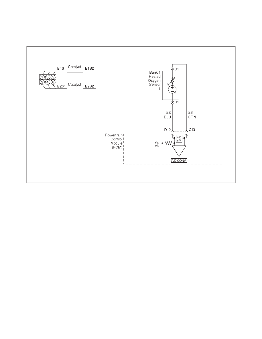
Diagnostic Trouble Code (DTC) P0137 HO2S Circuit Low Voltage Bank 1
Sensor 2
D06RW082
Circuit Description
The powertrain control module (PCM) supplies bias
voltage of about 450 mV between the heated oxygen
sensor (HO2S) signal high and signal low circuits. When
measured with a 10 megaohm impedance digital
voltmeter, this may display as low as 350 mV. The oxygen
sensor varies the voltage within a range of about 1000 mV
when exhaust is rich, down through about 10 mV when
the exhaust is lean. The PCM constantly monitors the
HO2S signal during “closed loop” operation and
compensates for a rich or lean condition by decreasing or
increasing injector pulse width as necessary. If the Bank
1 HO2S 2 signal voltage remains excessively low for an
extended period of time, DTC P0137 will be set.
Conditions for Setting the DTC
f
No related DTCs.
f
Engine is operating in “closed loop.”
f
Engine coolant temperature is above 60
°
C (140
°
F).
f
“Closed loop” commanded air/fuel ratio is between
14.5 and 14.8.
f
Throttle angle is between 3% and 19%.
f
Bank 1 HO2S 2 signal voltage remains below 22 mV
during normal “closed loop” operation for a total of 106
seconds over a 125-second period of time.
OR
f
Bank 1 HO2S 2 signal voltage remains below 400 mV
during power enrichment mode fuel control operation
for up to 5 seconds.
Action Taken When the DTC Sets
f
The PCM will illuminate the malfunction indicator lamp
(MIL) the first time the fault is detected.
f
The PCM will store conditions which were present
when the DTC set as Freeze Frame and in the Failure
Records data.
Conditions for Clearing the MIL/DTC
f
The PCM will turn the MIL “OFF” on the third
consecutive trip cycle during which the diagnostic has
been run and the fault condition is no longer present.
f
A history DTC P0137 will clear after 40 consecutive
warm-up cycles have occurred without a fault.
f
DTC P0137 can be cleared by using the Tech 2 “Clear
Info” function or by disconnecting the PCM battery
feed.
Diagnostic Aids
Check for the following conditions:
f
Heated oxygen sensor wiring – The sensor pigtail may
be mispositioned and contacting the exhaust system.
f
Poor PCM to engine grounds.
f
Fuel pressure – A condition which causes a lean
exhaust can cause DTC P0137 to set. The system will
go lean if pressure is too low. The PCM can
compensate for some decrease. However, if fuel

6E2–178
RODEO 6VD1 3.2L ENGINE DRIVEABILITY AND EMISSIONS
pressure is too low, a DTC P0137 may be set. Refer
to
Fuel System Diagnosis.
f
Lean injector(s) – Perform “Injector Balance Test.”
f
Vacuum leaks – Check for disconnected or damaged
vacuum hoses and for vacuum leaks at the intake
manifold, throttle body, EGR system, and PCV system.
f
Exhaust leaks – An exhaust leak may cause outside air
to be pulled into the exhaust gas stream past the
HO2S, causing the DTC P0137 to set. Check for
exhaust leaks near the Bank 1 HO2S 2 sensor.
f
MAF sensor – The system can go lean if the MAF
sensor signal indicates an engine airflow
measurement that is not correct. Disconnect the MAF
sensor to see if the lean condition is corrected. If so,
replace the MAF sensor.
f
Fuel contamination – Water, even in small amounts,
can be delivered to the fuel injectors. The water can
cause a lean exhaust to be indicated. Excessive
alcohol in the fuel can also cause this condition. Refer
to
Fuel System Diagnosis for procedure to check for
fuel contamination.
f
If none of the above conditions are present, replace the
affected HO2S.
Test Description
Number(s) below refer to the step number(s) on the
Diagnostic Chart.
3. DTC P0137 failing during operation may indicate a
condition described in the “Diagnostic Aids” above.
If the DTC P0137 test passes while the Failure
Records conditions are being duplicated, an
intermittent condition is indicated.
Reviewing the Failure Records vehicle mileage since the
diagnostic test last failed may help determine how often
the condition that caused the DTC to be set occurs. This
may assist in diagnosing the condition.
DTC P0137 –HO2S Circuit Low Voltage Bank 1 Sensor 2
Step
Action
Value(s)
Yes
No
1
Was the “On-Board Diagnostic (OBD) System Check”
performed?
—
Go to
Step 2
Go to
OBD
System
Check
2
1. Install the Tech 2.
2. Run the engine at operating temperature.
3. Operate the vehicle within the parameters specified
under “Conditions for Setting the DTC” criteria
included in Diagnostic Support.
4. Using a Tech 2, monitor Bank 1 HO2S 2 voltage.
Does the Bank 1 HO2S 2 voltage remain below the
specified value?
22 mV
Go to
Step 4
Go to
Step 3
3
1. Ignition “ON,” engine “OFF,” review and record Tech
2 Failure Records data and note parameters.
2. Operate the vehicle within Failure Records
conditions as noted.
3. Using a Tech 2, monitor “DTC” info for DTC P0137
until the DTC P0137 test runs.
4. Note the test result.
Does the Tech 2 indicate DTC P0137 failed this
ignition?
—
Go to
Step 4
Refer to
Diagnostic
Aids
4
1. Turn ignition “OFF.”
2. Disconnect the PCM.
3. Check the Bank 1 HO2S 2 high and low signal
circuits for a short to ground or a short to the heater
ground circuit.
Were Bank 1 HO2S 2 signal circuits shorted?
—
Go to
Step 5
Go to
Step 6
5
Repair the Bank 1 HO2S 2 signal circuit.
Is the action complete?
—
Verify repair
—
6
1. Ignition “OFF.”
2. Leave the PCM and HO2S 2 disconnected.
3. Check for continuity between the high and low
signal circuits.
Was there continuity between the high and low circuits?
—
Go to
Step 7
Go to
Step 8
Нет комментариевНе стесняйтесь поделиться с нами вашим ценным мнением.
Текст