Isuzu Rodeo UE. Manual — part 34

2A–32 POWER–ASSISTED STEERING SYSTEM
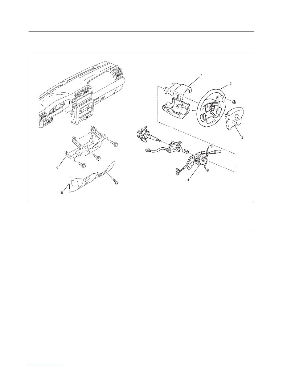
Steering Wheel
Steering Wheel and Associated Parts
827RW069
Legend
(1) Horn Lead
(2) SRS Connector
(3) Steering Wheel
(4) Steering Wheel Fixing Nut
(5) Inflator Module
CAUTION: Once the steering column is removed
from the vehicle, the column is extremely
susceptible to damage. Dropping the column
assembly on its end could collapse the steering shaft
or loosen the slide block which maintains column
rigidity. Leaning on the column assembly could
cause the jacket to bend or deform. Any of the above
damage could impair the column’s collapsible
design. If it is necessary to remove the steering
wheel, use only the specified steering wheel puller.
Under no conditions should the end of the shaft be
hammered upon, as hammering could loosen slide
block which maintains column rigidity.
Removal
1. Turn the steering wheel so that the vehicle’s wheels
are pointing straight ahead.
2. Turn the ignition switch to “LOCK”.
3. Disconnect the battery “–” terminal cable, and wait at
least 5 minutes.
4. Disconnect the yellow 2-way SRS connector located
under the steering column.
POWER–ASSISTED STEERING SYSTEM
2A–33
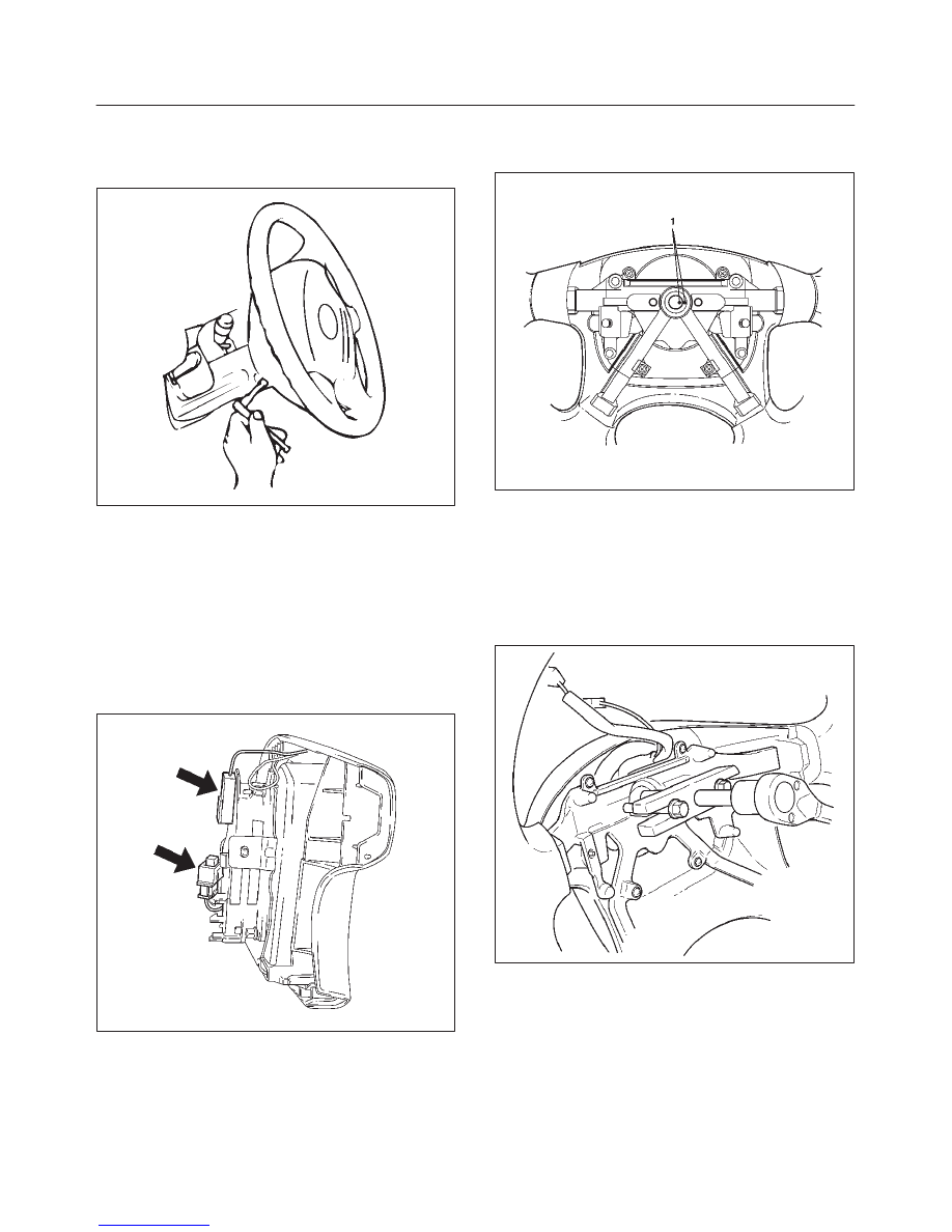
5. Loosen the inflator module fixing bolt from behind the
steering wheel assembly using a TORX
driver or
equivalent until the inflator module can be released
from steering assembly.
827RW070
6. Disconnect the yellow 2-way SRS connector located
behind the inflator module.
WARNING: THE INFLATOR MODULE SHOULD
ALWAYS BE CARRIED WITH THE URETHANE
COVER AWAY FROM YOUR BODY AND SHOULD
ALWAYS BE LAID ON A FLAT SURFACE WITH THE
URETHANE SIDE UP. THIS IS NECESSARY
BECAUSE A FREE SPACE IS PROVIDED TO ALLOW
THE AIR CUSHION TO EXPAND IN THE UNLIKELY
EVENT OF ACCIDENTAL DEPLOYMENT.
OTHERWISE, PERSONAL INJURY MAY RESULT.
827RW073
7. Disconnect horn lead.
8. Remove steering wheel fixing nut.
9. Apply a setting mark (1) across the steering wheel
and shaft so parts can be reassembled in their original
position, then remove steering wheel.
430RW021
10. Move the front wheels to the straight ahead position,
then use steering wheel remover J–29752 to remove
the steering wheel.
CAUTION: Never apply force to the steering wheel
in direction of the shaft by using a hammer or other
impact tools in an attempt to remove the steering
wheel. The steering shaft is designed as an energy
absorbing unit.
430RX005
2A–34 POWER–ASSISTED STEERING SYSTEM
Installation
1. Install steering wheel by aligning the setting marks
made when removing.
CAUTION: Never apply force to the steering wheel
in direction of the shaft by using a hammer or other
impact tools in an attempt to remove the steering
wheel. The steering shaft is designed as an energy
absorbing unit.
2. Tighten the steering wheel fixing nut to the specified
torque.
Torque: 34 N·m (25 lb ft)
3. Connect horn lead.
4. Support the module and carefully connect the SRS
connector.
NOTE: Pass the lead wire through the tabs on the plastic
cover (wire protector) of inflator to prevent lead wire from
being pinches.
5. Tighten bolts to specified torque.
Torque: 9 N·m (78 lb in)
6. Connect the yellow 2-way SRS connector located
under the steering column.
7. Connect the battery “–” terminal cable.
8. Turn the ignition switch to “ON” while watching
warning light. Light should flash 7 times and then go
off. If lamp does not operate correctly, refer to
Restraints section.
POWER–ASSISTED STEERING SYSTEM
2A–35
Combination Switch
Combination Switch and Associated Parts
431RX006
Legend
(1) Steering Column Cover
(2) Steering Wheel
(3) Inflator Module
(4) Combination Switch and SRS Coil Assembly
(5) Instrument Panel Lower Cover
(6) Driver Knee Bolster (reinforcement)
Removal
1. Turn the steering wheel so that the vehicle’s wheels
are pointing straight ahead.
2. Turn the ignition switch to “LOCK”.
3. Disconnect the battery “–” terminal cable, and wait at
least 5 minutes.
4. Disconnect the yellow 2-way SRS connector located
under the steering column.
CAUTION: The wheels of the vehicle must be
straight ahead and the steering column in the
“LOCK” position before disconnecting the steering
wheel. Failure to do so will cause the coil assembly
to become uncentered which will cause damage to
the coil assembly.
5. Remove the engine hood opening lever, then remove
instrument panel lower cover.
6. Remove the driver knee bolster (reinforcement).
Нет комментариевНе стесняйтесь поделиться с нами вашим ценным мнением.
Текст