Isuzu Rodeo UE. Manual — part 484

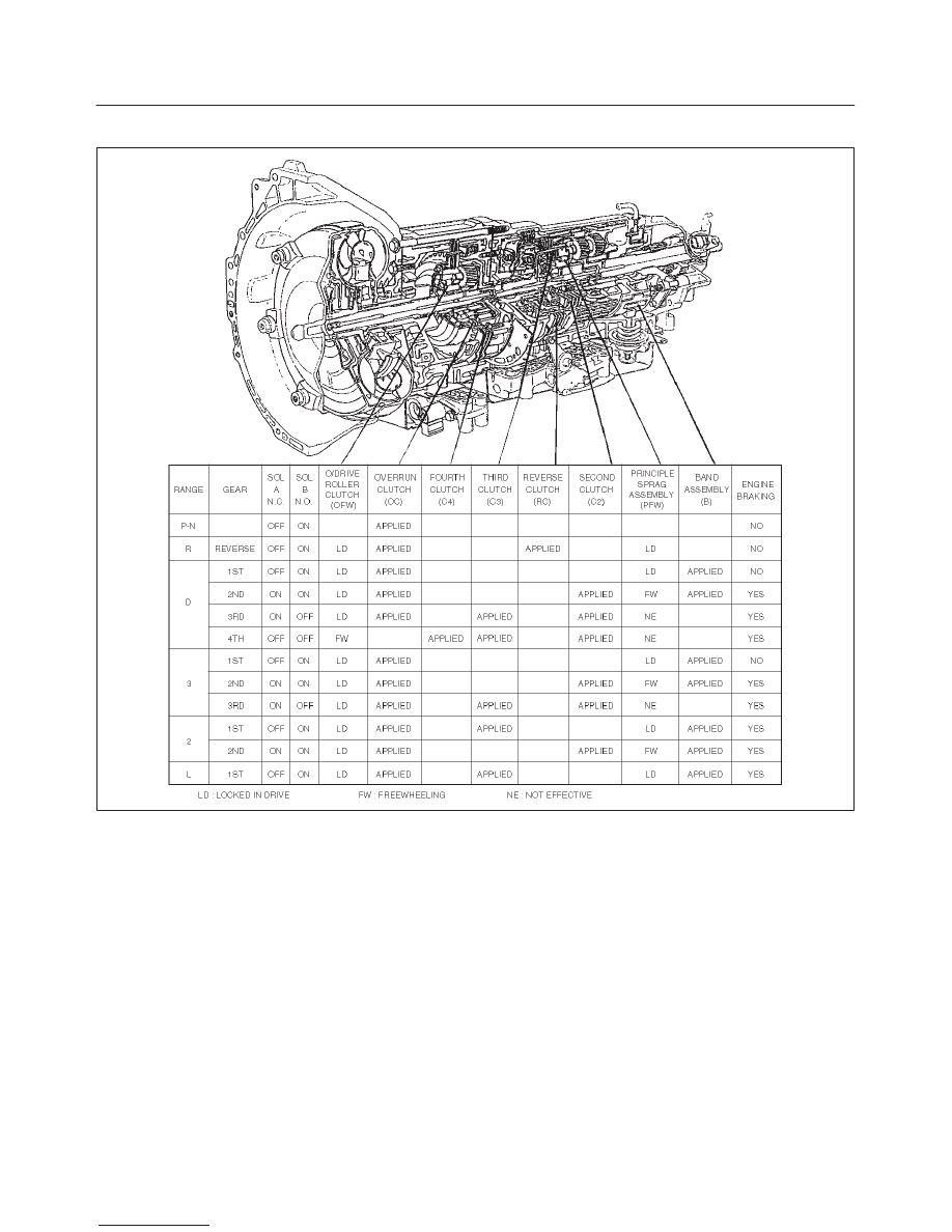
TRANSMISSION CONTROL SYSTEM (4L30–E)
7A1–55
DTC P0724 TCC Brake Switch Circuit Low (Stuck Off)
D07RW021
Circuit Description
The TCC brake switch is used to indicate brake pedal
status. The normally opened brake switch signal voltage
supplies a B+ signal on circuit GRN/YEL to the PCM when
the brakes are applied. The PCM uses this signal to
deenergize the TCC solenoid when the brakes are
applied.
This DTC detects an open brake switch during
decelerations. This is a type “D” DTC.
Conditions For Setting The DTC
f
No OSS DTCs P0722 or P0723.
f
The PCM detects an open brake switch/circuit (0
volts) during decelerations and the following events
occur seven consecutive times: vehicle speed is
greater than 32 km/h (20 mph) for 4 seconds; then
vehicle speed is between 8 and 32 km/h (5 and 20
mph) for 4 seconds; then vehicle speed is less than 8
km/h (5 mph).
Action Taken When The DTC Sets
f
The PCM will not illuminate the Malfunction Indicator
Lamp (MIL).
Conditions For Clearing The DTC
f
The DTC can be cleared from the PCM history by
using a scan tool.
f
The DTC will also be cleared from history when the
vehicle has achieved 40 warmup cycles without a
failure reported.
f
The PCM will cancel the DTC default actions when
the fault no longer exists and the ignition is cycled “off”
long enough to power down the PCM.
Diagnostic Aids
f
Inspect the wiring for poor electrical connection at the
PCM. Look for possible bent, backed out, deformed
or damaged terminals. Check for weak terminal
tension as well. Also check for a chafed wire that
could short to bare metal or other wiring. Inspect for a
broken wire inside the insulation.
f
When diagnosing for a possible intermittent short or
open condition, move the wiring harness while
observing test equipment for a change.
f
Check customer driving habits and/or unusual traffic
conditions (i.e. stop and go, expressway).
f
Check brake switch for proper mounting and
adjustment.
Test Description
The numbers below refer to the step numbers on the
diagnostic chart:
3. This test checks for voltage at the brake switch.
6. This test checks the brake switch.
7A1–56 TRANSMISSION CONTROL SYSTEM (4L30–E)
DTC P0724 TCC Brake Switch Circuit Low (Stuck Off)
Step
Action
Yes
No
1
Were you sent here from the “Powertrain On–Board Diagnostic
(OBD) System Check”?
Go to Step 2
Go to OBD
System Check
Refer to
Driveability and
Emissions in
Engine section
2
1. Install the scan tool.
2. With the engine “off”, turn the ignition switch “on”.
NOTE: Before clearing DTC(s), use the scan tool to record “Failure
Records” for reference, as data will be lost when the “Clear Info”
function is used.
3. Record the DTC “Failure Records”.
4. Apply then release the brake pedal.
Does the scan tool display “TCC Brake Switch” as “closed” with
the brake pedal applied, and then display “open” when the brake
pedal is released?
Go to Diagnostic
Aids
Go to Step 3
3
1. Connect the test light to ground.
2. Back probe ignition feed circuit terminal I18–1 at the brake
switch.
Is the test light “on”?
Go to Step 4
Go to Step 5
4
1. Connect the test light to ground.
2. Back probe circuit terminal I18–4 at the brake switch.
3. Apply the brake pedal.
Is the test light “on” when the brake pedal is applied?
Go to Step 7
Go to Step 6
5
Repair the open in ignition feed circuit terminal I18–1 to the brake
switch. If fuse is open, check circuit terminal I18–4.
Is the repair complete?
Go to Step 11
—
6
1. Disconnect I18 connector.
2. Check the resistance between terminal I18–1 and I18–4.
Is the resistance 0 ohm with the brake pedal applied?
Go to Step 7
Go to Step 8
7
Check circuit terminal I18–4 for a open.
Was a problem found?
Go to Step 11
Go to Step 9
8
Replace the brake switch.
Is the replacement complete?
Go to Step 11
—
9
Check PCM for faulty connections.
Was a problem found?
Go to Step 11
Go to Step 10
10
Replace the PCM. Refer to Powertrain Control Module (PCM) in
Automatic Transmission (4L30–E) section.
Is the replacement complete?
Go to Step 11
—
11
1. After the repair is complete, use the scan tool to select “DTC”,
then “Clear Info” function and ensure the following conditions
are met:
The PCM brake switch signal must indicate 12 volts for 1
seconds with the brake pedal released.
2. Review the scan tool “DTC Info”.
Has the last test failed or is the current DTC displayed?
Begin diagnosis
again
Go to Step 1
Repair verified
Exit DTC table
TRANSMISSION CONTROL SYSTEM (4L30–E)
7A1–57
DTC P0730 Transmission Incorrect Gear Ratio
D07RT015
Circuit Description
f
The Powertrain Control Module (PCM) calculates the
slippage of the converter and transmission based
upon the engine speed, the output speed, and the
current gear ratio.
f
The slippage of the converter at a high enough engine
speed is low. The transmission should not slip more
than a given value when there is no shift.
f
This DTC detects a slip at each gear. This is a type
“C” DTC.
Conditions For Setting The DTC
f
No Output Speed Sensor DTC(s) P0722, P0723.
f
Not in Park, Neutral or Reverse.
f
Engine speed is greater than 3500 rpm.
f
3 seconds since upshift.
f
3 seconds since downshift.
f
3 seconds since garage shift (N
→
D).
f
And one of the following conditions occur:
– Slip is greater than 753 rpm in 1st gear.
– Slip is greater than 713 rpm in 2nd gear.
– Slip is greater than 694 rpm on 3rd gear.
– Slip is greater than 685 rpm on 4th gear.
f
All conditions met for 5.5 seconds.
Action Taken When The DTC Sets
f
Maximum line pressure.
f
The PCM will not illuminate the Malfunction Indicator
Lamp (MIL).
f
The PCM will illuminate the CHECK TRANS Lamp.

7A1–58 TRANSMISSION CONTROL SYSTEM (4L30–E)
Conditions For Clearing The DTC/CHECK
TRANS Lamp
f
The PCM will turn “off” the CHECK TRANS Lamp
after three consecutive ignition cycles without a
failure reported.
f
The DTC can be cleared from PCM memory by using
a scan tool. The DTC can also be cleared from
memory when the vehicle has made 40 warmup
cycles without a failure reported.
f
The PCM will cancel the DTC Actions Taken items
when the fault conditions no longer exist and the
ignition is cycles “off” long enough to power down the
PCM.
Diagnostic Aids
f
Check for intermittent output speed sensor circuit
problems.
f
Check for possible incorrect calibration. (PCM part
No., tire specifications, and rear axle ratio)
Test Description
The numbers below refer to the step numbers on the
diagnostic chart:
3. This step checks for possible low fluid level causing
slipping resulting in an undefined gear ratio.
4. This step checks for correct gear ratios for
commanded gears.
5. This step checks for low line pressure.
DTC P0730 Transmission Incorrect Gear Ratio
Step
Action
Yes
No
1
Were you sent here from the “On–Board Diagnostic (OBD)
System Check”?
Go to Step 2
Go to OBD
System Check
Refer to
Driveability and
Emission in
Engine section
2
Visually inspect the transmission cooling system for fluid leaks.
f
Refer to Chart 16: Possible Causes of Transmission Fluid
Leaks of Mechanical/Hydraulic Diagnosis Symptoms Index in
Automatic Transmission (4L30–E) section.
Was condition found and corrected?
Go to Step 7
Go to Step 3
3
Refer to Checking Transmission Fluid Level and Condition in
Automatic Transmission (4L30–E) section.
Has transmission fluid checking procedure been performed?
Go to Step 4
Go to Checking
Transmission
Fluid Level and
Condition in
Automatic
Transmission
(4L30–E) section
4
1. Install the scan tool.
2. Turn the ignition switch to the “on” position.
3. Engine not running.
NOTE: Before clearing DTC(s) use the scan tool to record the
“Failure Records” for reference, as data will be lost when the “Clear
Info” function is used.
4. Record the Failure Record data.
5. Use the scan tool snapshot mode to record transmission gear
ratios.
6. Drive vehicle in transmission gear ranges 1, 2, 3, and D with
the engine speed is greater than 3,500 rpm for 5.5 seconds.
7. Record each transmission gear.
1st:2.73 – 2.99
2nd:1.54 – 1.71
3rd:0.93 – 1.05
4th:0.66 – 0.78
Does commanded gear ratio match ranges as shown?
Refer to
Diagnostic Aids
Go to Step 5
Нет комментариевНе стесняйтесь поделиться с нами вашим ценным мнением.
Текст