Isuzu Rodeo UE. Manual — part 292
6A–81
ENGINE MECHANICAL (6VD1 3.2L)
5. Remove the rod caps.
6. Measure the width of the plastigage and
determine the oil clearance. If the oil clearance
exceeds the limit, replace the rod bearing as a
set.
Standard : 0.019 mm–0.043 mm
(0.0007 in–0.0017 in)
Limit : 0.08 mm (0.0031 in)
015RS008
7. Clean the plastigage from the bearings and the
crankshaft pins.
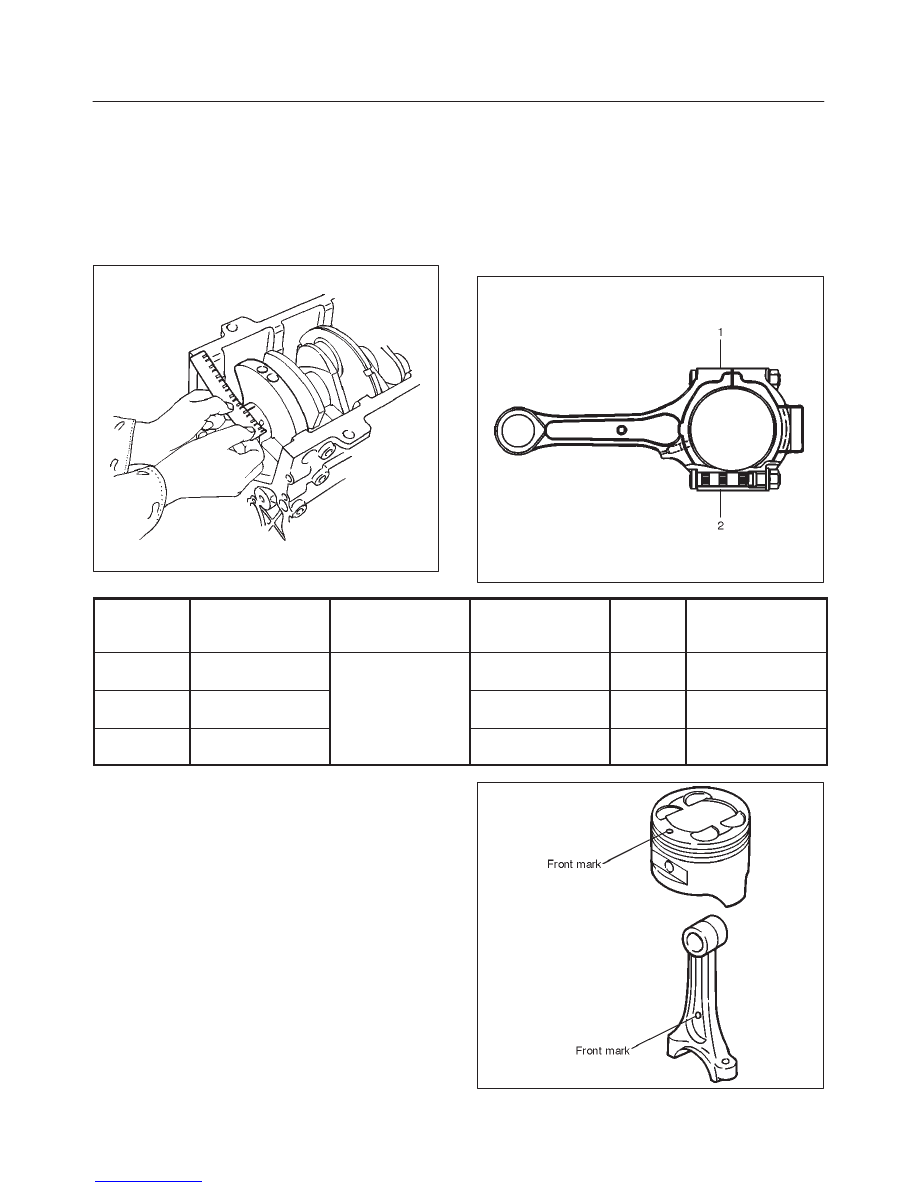
Con–rod Bearing Selection
Select and install the new connecting rod bearings,
paying close attention to the connecting rod big end
diameter size mark (1).
NOTE: Take care not to confuse the alignment mark (2)
and the size mark (1) during the installation procedure.
015RS034
1 Size Mark
Big end Bore
Diameter
Crankshaft Pin
Diameter
Connecting Rod
Bearing Thickness
(Reference)
Color of
Size
Mark
Oil Clearance
(Reference)
A
56.994-57.000
(2.2439-2.2441)
1.512-1.516
(0.0595-0.0597)
Yellow
0.025-0.054
(0.0010-0.0021)
B
56.988-56.994
(2.2436-2.2439)
53.922-53.937
(2.1229-2.1235)
1.508-1.512
(0.0594-0.0595)
Green
0.027-0.056
(0.0011-0.0022)
C
56.982-56.988
(2.2434-2.2436)
1.504-1.508
(0.0592-0.0594)
Pink
0.029-0.058
(0.0011-0.0023)
Reassembly
1. Install connecting rod
2. Install piston
3. Install piston pin
f
Apply a thin coat of engine oil to the piston pin. Try to
insert the piston pin into the piston pin hole with
normal finger pressure.
NOTE: When changing piston / connecting rod
combinations, do not change the piston / piston pin
combination and do not reuse the old piston pin.
f
Attach the piston to the connecting rod with the
piston front mark and the connecting rod front mark
on the same side.
015RS036
6A–82
ENGINE MECHANICAL (6VD1 3.2L)
f
With J–24086–C Piston pin service set and a press,
press fit the piston pin.
NOTE: Heat the connecting rod small end to a suitable
temperature to ensure smooth installation.
015RS037
Legend
(1) Press Ram
(2) Piston
(3) Connecting Rod
(4) Piston Pin
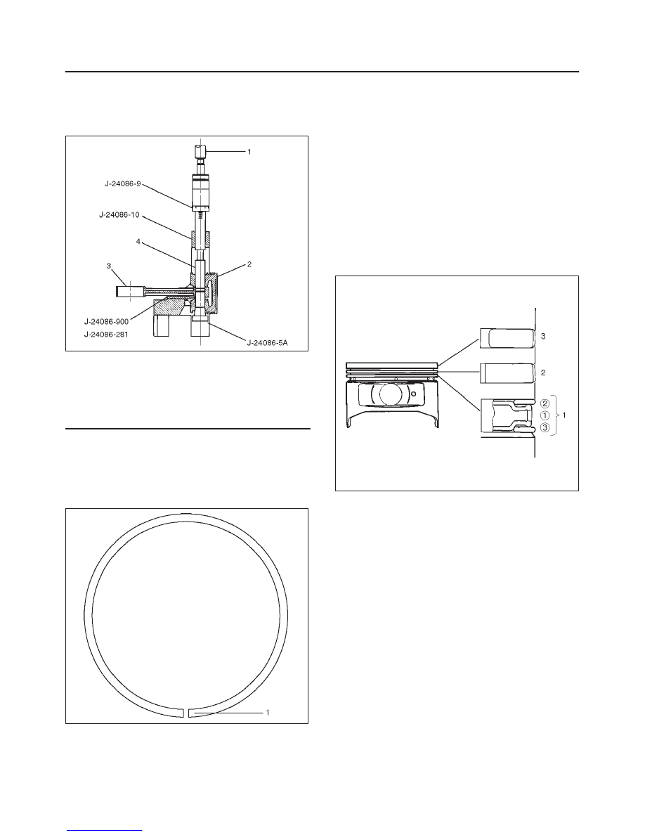
4. Install piston ring with the piston ring expander.
The compression ring must be set with the T mark (1)
facing up.
Marked T : No.1 Compression ring
Marked T2 : No.2 Compression ring
015RS027
f
Install piston rings in the following sequence.
1. Oil ring
1. Expander ring
2. Upper side rail
3. Lower side rail
2. 2nd compression ring
3. 1st compression ring
f
The compression rings must be set with the T or T2
mark facing up.
Marked T : No.1 Compression ring
Marked T2 : No.2 Compression ring
f
After installation, apply engine oil to the entire
circumference of the piston rings. Check to see that
all the rings rotate smoothly.
015RS038
5. Install piston and connecting rod assembly.
f
Insert the bearings into the connecting rods and
caps. Apply new engine oil to the bearing faces and
nuts.
f
Tighten the connecting rod cap nuts
Torque : 54 N·m (40 lb ft)
NOTE: Do not apply engine oil to the bearing back faces.
6. Oil gallery, refer to “Crankshaft and main bearing” in
this manual.
7. Oil strainer and O-ring.
8. Oil pipe and O-ring.
9. Install crankcase with oil pan, refer to “Oil pan and
Crankcase” in this manual.
10. Install cylinder head gasket.
11. Install Cylinder head assembly.
f
Refer to “Cylinder head” in this manual.
6A–83
ENGINE MECHANICAL (6VD1 3.2L)
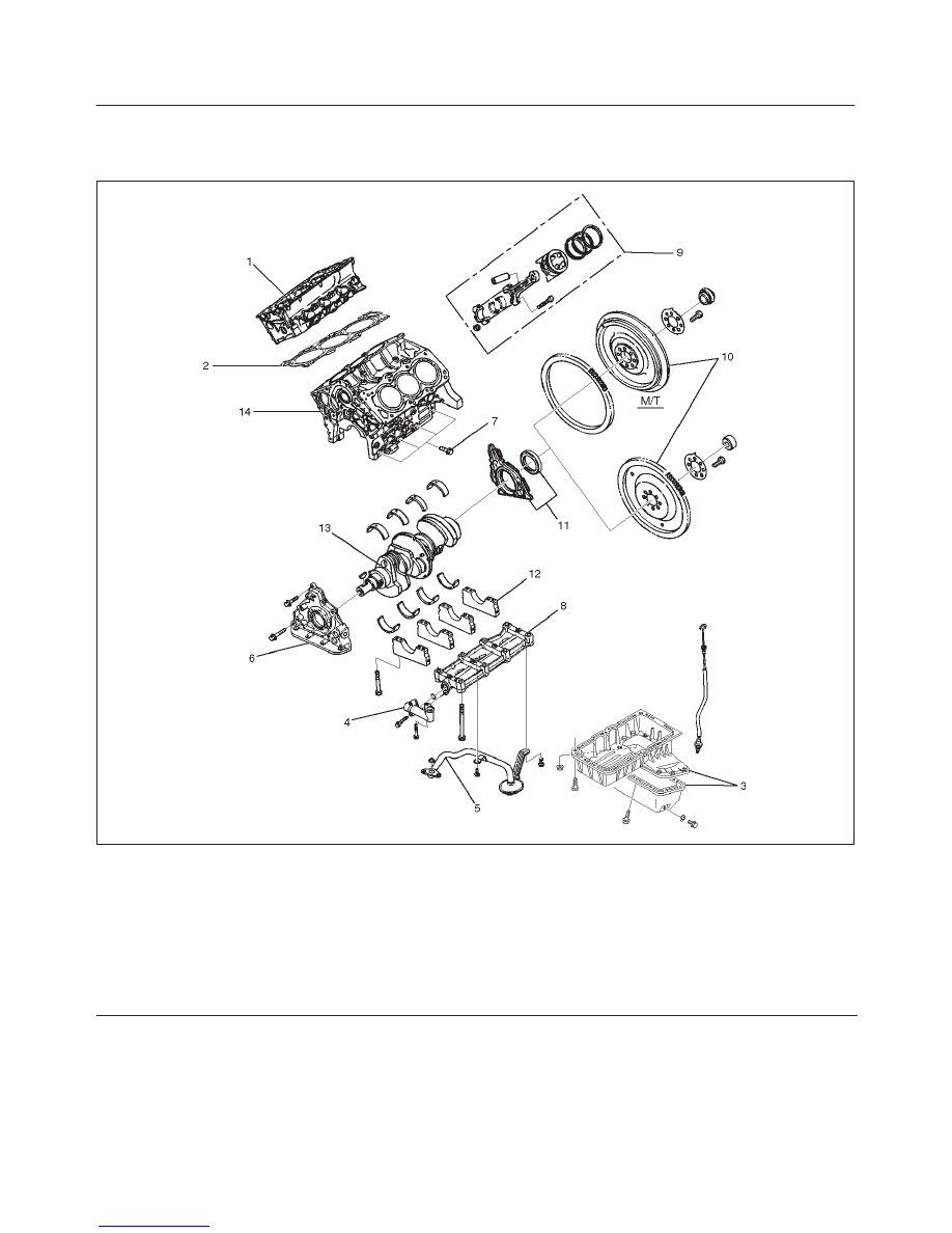
Cylinder Block
Cylinder Block and Associated Parts
012RW010
Legend
(1) Cylinder Head Assembly
(2) Cylinder Head Gasket
(3) Crankcase with Oil Pan
(4) Oil Pipe and O-ring
(5) Oil Strainer and O-ring
(6) Oil Pump Assembly
(7) Cylinder Block Side Bolts
(8) Oil Gallery
(9) Piston and Connecting Rod Assembly
(10) Flywheel
(11) Rear Oil Seal Retainer Assembly
(12) Main Bearing Cap
(13) Crankshaft
(14) Cylinder Block
Disassembly
1. Remove cylinder head assembly.
2. Remove cylinder head gasket.
3. Remove crankcase with oil pan.
4. Remove oil pipe and O-ring.
5. Remove oil strainer and O-ring.
6. Remove oil pump assembly.
7. Remove crankcase side bolts.
8. Remove oil gallery.
9. Remove piston and connecting rod assembly.
10. Remove flywheel.
6A–84
ENGINE MECHANICAL (6VD1 3.2L)
11. Remove rear oil seal retainer assembly.
12. Remove main bearing cap.
13. Remove crankshaft.
14. Remove cylinder block.
Inspection and Repair
1. Remove the cylinder head gasket and any other
material adhering to the upper surface of the cylinder
block. Be very careful not to allow any material to
accidentally drop into the cylinder block. Be very
careful not to scratch the cylinder block.
2. Carefully remove the oil pump, rear oil seal retainer,
and crankcase assembly installation surface seal.
3. Wipe the cylinder block clean.
4. Visually inspect the cylinder block. If necessary, use a
flaw detector to perform a dye penetrate and
hydraulic (or air pressure) test. If cracking or other
damage is discovered, the cylinder block must either
be repaired or replaced.
Flatness
1. Using a straight–edge and feeler gauge, check that
the upper surface of the cylinder block is not warped.
CAUTION: Be very careful not to allow any material
to accidentally drop into the upper surface of the
cylinder block. Be very careful not to scratch the
upper surface of the cylinder block.
2. The cylinder block must be reground or replaced if the
warpage exceeds the limit.
Warpage
Limit : 0.15 mm (0.0059 in)
Maximum repairable limit: 0.15 mm (0.0059 in)
012RS004
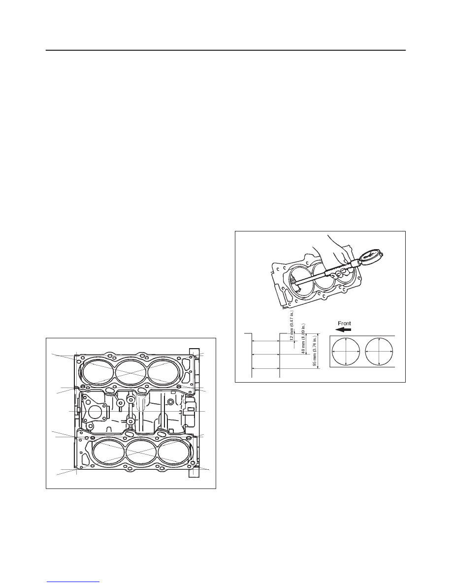
Cylinder Bore
Use a cylinder gauge to measure the cylinder bore
diameter in both the axial and thrust directions. Each
measurement should be made at six points.
CAUTION: Be very careful not to allow any material
to accidentally drop into the upper surface of the
cylinder block. Be very careful not to scratch the
upper surface of the cylinder block.
Cylinder Bore Inside Diameter
Limit : 93.530 (3.6823)
If the measurement exceed the specified limit, the
cylinder block must be replaced.
Diameter
Grade A : 93.400 mm–93.410 mm
(3.6772 in–3.6776 in)
Grade B : 93.411 mm–93.420 mm
(3.6776 in–3.6779 in)
Grade C : 93.421 mm–93.430 mm
(3.6780 in–3.6783 in)
012RS005
NOTE: For information on piston diameter, please refer
to the section ”Inspection of the Piston and Connecting
Rod Assembly” in this manual.
Нет комментариевНе стесняйтесь поделиться с нами вашим ценным мнением.
Текст