Isuzu Rodeo UE. Manual — part 309

6D3–17
STARTING AND CHARGING SYSTEM (6VD1 3.2L)
150RW029

6D3–18 STARTING AND CHARGING SYSTEM (6VD1 3.2L)
Charging System
General Description
The IC integral regulator charging system and its main
components are connected as shown in illustration.
The regulator is a solid state type and it is mounted along
with the brush holder assembly inside the generator
installed on the rear end cover.
The generator does not require particular maintenance
such as voltage adjustment.
The rectifier connected to the stator coil has diodes to
transform AC voltage into DC voltage.
This DC voltage is connected to the output terminal of
generator.
F06RX002
General On–Vehicle Inspection
A basic wiring diagram is shown in the illustration. When
operating normally, the indicator bulb will come on when
the switch is turned on, and will then go out when the
engine starts. If the indicator operates abnormally, or if an
undercharged or overcharged battery condition occurs,
the following procedure may be used to diagnose the
charging system. Remember that an undercharged
battery is often caused by accessories being left on
overnight, or by a defective switch which allows a bulb,
such as a trunk or glove box light, to stay on.
OBSERVE THE FOLLOWING PROCEDURE:
1. Visually check belt and wiring.
2. Go to step 5. for vehicles without charge indicator
light.
3. Switch on, engine stopped, light should be on. If not,
detach harness at generator, ground “L” terminal
lead.
a. Lamp lights, replace or repair generator.
b. Lamp dose not light, locate open circuit between
grounding lead and ignition switch. Bulb may be
open.
4. Switch on, engine running at moderate speed. Light
should be off. If not, detach wiring harness at
generator.
a. If light goes off, replace or repair generator.
b. If light stays on, check for grounded “L” terminal
wire in harness.
5. Battery undercharged or overcharged.
a. Detach wiring harness connector from generator.
b. With switch on, engine not running connect
voltmeter from ground to “L” terminal in wiring
harness, and to “IG” terminal. If used. Wiring
harness may connect to either “L” or “IG” or both.
c. Zero reading indicates open circuit between
terminal and battery. Connect as required.
6D3–19
STARTING AND CHARGING SYSTEM (6VD1 3.2L)
d. Re-connect harness connector to generator, run
engine at moderate speed, with electrical
accessories turned off.
e. Measure voltage across battery. If above 16.0V,
replace or repair generator.
f. Connect ammeter at generator output terminal.
Turn on accessories, load battery with carbon pile
to obtain maximum amperes output.
Maintain voltage at 13.0V or above.
1. If within 15 amperes of rated output, generator is
OK.
2. If not within 15 amperes of rated output, replace or
repair generator.
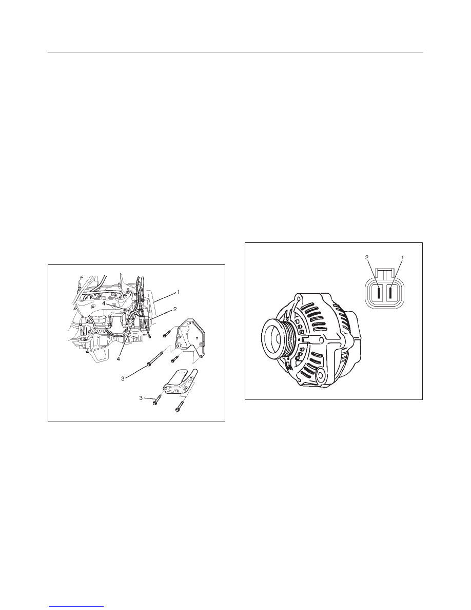
Generator
Removal
1. Disconnect battery ground cable.
2. Move drive belt tensioner to loose side using wrench
then remove drive belt (1).
3. Disconnect the wire from terminal “B” and disconnect
the connector (4).
4. Remove generator fixing bolt (3).
5. Remove generator assembly (2).
060RW002
Inspection
1. Disconnect the wiring connector from generator.
2. With the engine stopped, turn starter switch to “on”
and connect a voltmeter between connector terminal
L (1) and ground or between terminal IG (2) and
ground.
066RX002
If voltage is not present, the line between battery and
connector is disconnected and so requires repair.
3. Reconnect the wiring connector to the generator, run
the engine at middle speed, and turn off all electrical
devices other than engine.
4. Measure battery voltage. If it exceeds 16V, repair or
replace the generator.
5. Connect an ammeter to output terminal of generator,
and measure output current under load by turning on
the other electrical devices (eg., headlights). At this
time the amperes must not be less than 15A and the
voltage must not be less than 13V.

6D3–20 STARTING AND CHARGING SYSTEM (6VD1 3.2L)
Installation
1. Install generator assembly to the position.
2. Install generator assembly and tighten the fixing bolts
to the specified torque.
Torque:
M10 bolt: 41 N·m (30 Ib ft)
M8 bolt: 21 N·m (15 Ib ft)
3. Connect wiring harness connector and direct terminal
“B”.
4. Move drive belt tensioner to loose side using wrench,
then install drive belt to normal position.
5. Reconnect battery ground cable.
Disassembled View
066RW022
Legend
(1) Pulley Nut
(2) Pulley
(3) Front Cover Assembly
(4) Rotor Assembly
(5) Stator Assembly
(6) Through Bolt
(7) Nut
(8) Terminal Insulator
(9) Rear Cover Assembly
(10) Rectifier
(11) Brush Holder Assembly
(12) Regulator Assembly
Нет комментариевНе стесняйтесь поделиться с нами вашим ценным мнением.
Текст