Isuzu Rodeo UE. Manual — part 412

6E2–403
RODEO 6VD1 3.2L ENGINE DRIVEABILITY AND EMISSIONS
f
EVAP purge solenoid driver circuit grounded
If any of these conditions are present, DTC P1441 will set.
Conditions for Setting the DTC
f
No TP sensor, ODM, IAT sensor, or MAP sensor DTCs
are set.
f
Intake air temperature is above 0
°
C (32
°
F).
f
Fuel tank level is between 15% and 85%.
f
A continuous open purge flow condition is detected
during the diagnostic test.
Action Taken When the DTC Sets
f
The PCM will illuminate the Malfunction Indicator lamp
(MIL) during the second key cycle trip in which the DTC
sets.
f
The PCM will store conditions which were present
when the DTC was set as Freeze Frame and in the
Failure Records data.
Conditions for Clearing the MIL/DTC
f
The PCM will turn the MIL “OFF” on the third
consecutive trip cycle during which the diagnostic has
been run and the fault condition is no longer present.
f
A history DTC P1441 will clear after 40 consecutive
warm-up cycles have occurred without a fault.
f
DTC P1441 can be cleared by using the Tech 2 “Clear
Info” function or by disconnecting the PCM battery
feed.
Diagnostic Aids
Check for the following conditions:
f
Poor connection at PCM. Inspect harness connectors
for backed-out terminals, improper mating, broken
locks, improperly formed or damaged terminals, and
poor terminal-to-wire connection.
f
Damaged harness. Inspect the wring harness for
damage. If the harness appears to be OK, connect the
EVAP pressure/purge cart J41413 to the EVAP service
port, pressurize the EVAP system to 10 in. H
2
O and
observe the “Fuel Tank Vacuum” display on the Tech
2 while moving connectors and wiring harnesses
related to the EVAP purge solenoid. A sudden change
in the display will indicate the location of the fault.
f
Incorrect vacuum line routing. Verify that the source
vacuum line routing to the EVAP purge solenoid is
correct and that the EVAP purge and source vacuum
lines to the EVAP purge solenoid are not switched.
Reviewing the Failure Records vehicle mileage since the
diagnostic test last failed may help determine how often
the condition that caused the DTC to be set occurs. This
may assist in diagnosing the condition.
Test Description
Number(s) below refer to the step number(s) on the
Diagnostic Chart.
2.If an EVAP purge solenoid electrical fault is present,
the purge system will not operate correctly.
repairing the electrical fault will very likely correct
the condition that set DTC P1441.
3.Checks the fuel tank vacuum sensor at ambient
pressure.
4.Checks for a stuck open EVAP purge solenoid.
5.Verifies that the fuel tank pressure sensor accurately
reacts to EVAP system pressure changes.
7.If the EVAP purge and engine vacuum lines are
switched at the EVAP purge solenoid, the solenoid
valve will leak vacuum.
DTC P1441 – EVAP System Flow During Non-Purge
Step
Action
Value(s)
Yes
No
1
Was the “On-Board Diagnostic (OBD) System Check”
performed?
—
Go to
Step 2
Go to
OBD
System
Check
2
1. Ignition “OFF.”
2. Remove the fuel filler cap.
3. Ignition “ON.” Observe “Fuel Tank Pressure” on the
Tech 2.
Is “Fuel Tank Pressure” at the specified value?
1.51 V
Go to
Step 3
Go to
P0452
or P0453

6E2–404
RODEO 6VD1 3.2L ENGINE DRIVEABILITY AND EMISSIONS
DTC P1441 – EVAP System Flow During Non-Purge
(Cont'd)
Step
No
Yes
Value(s)
Action
3
1. Re–install the fuel filler cap.
2. Using the Tech 2, command the EVAP Vent
Solenoid Valve “ON” (Closed).
3. Disconnect the canister side rubber hose end that
hose is connected between the Purge Solenoid
Valve and Canister.
IMPORTANT: Before continuing with the diagnosis,
zero the EVAP pressure and vacuum gauges on EVAP
pressure / purge cart J41413 (refer to the tool operating
instructions).
And then monitor the fuel tank inner pressure using the
Tech 2.
Does the fuel tank pressure hold the specified value?
1.52 - 1.60 V
Go to
Step 4
Go to
Step 6
4
1. Disconnect the EVAP pressure / purge cart J41413,
and then plug the hose end.
2. Disconnect the rubber hose end of engine vacuum
source side, (the hose is connected between Purge
Solenoid Valve and engine).
3. Connect a vacuum hand pump to this rubber hose
end.
4. Then apply -15 in H2O vacuum by the vacuum
pump.
5. Monitor the fuel tank inner pressure using the Tech
2.
Does the fuel tank inner pressure hold the specified
value?
1.47 - 1.51 V
Go to
Step 6
Go to
Step 5
5
Replace the Purge Solenoid Valve.
—
Verify repair
—
6
1. Check the leak, kinks or pinched hoses at the EVAP
system rubber hose line, and also check if the
rubber hoses are correctly connected or not.
2. Check for a leak from Vent Solenoid Valve and
EVAP system rubber hoses, and also check for
clogged Filter of air separator which is located near
the vent solenoid valve.
Was a problem found? Using the Vacuum Hose
Routing Diagram, repair or re-connect the rubber
hoses correctly.
—
Verify repair
Go to
Step 7
7
1. Start engine.
2. Remove the Fuel Filler Cap.
3. Using the Tech 2, command the EVAP Vent
Solenoid Valve “ON” (closed) and Purge Solenoid
Valve “OFF” (0%).
4. Replace the Fuel Filler Cap.
5. Run the engine at 2500RPM constant while
monitoring “Fuel Tank Vacuum” on the Tech 2.
Does the fuel tank vacuum remain at the specified
value while the EVAP Vent Solenoid Valve “ON”
(closed) and Purge Solenoid Valve “OFF” (o%)?
30 - 40%
Verify repair
Go to
Diagnostic
Aids
6E2–405
RODEO 6VD1 3.2L ENGINE DRIVEABILITY AND EMISSIONS
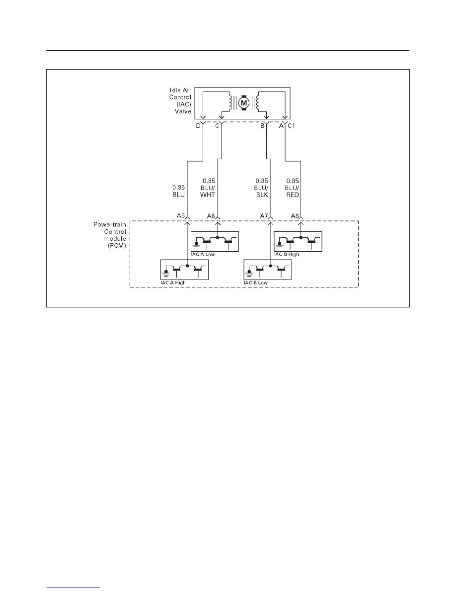
Diagnostic Trouble Code (DTC) P1508 IAC System Low RPM
T321115
Circuit Description
The powertrain control module (PCM) controls engine
idle speed by adjusting the position of the idle air control
(IAC) motor pintle. The IAC is a bi-directional stepper
motor driven by two coils. The PCM applies current to the
IAC coils in steps (counts) to extend the IAC pintle into a
passage in the throttle body to decrease air flow. The
PCM reverses the current to retract the pintle, increasing
air flow. This method allows highly accurate control of idle
speed and quick response to changes in engine load. If
the PCM detects a condition where too low of an idle
speed is present and the PCM is unable to adjust idle
speed by increasing the IAC counts, DTC P1508 will set,
indicating a problem with the idle control system.
Conditions for Setting the DTC
f
No Tech 2 test is being run.
f
None of these DTCs are set: TP sensor, VSS, ECT,
EGR, fuel system, MAF, MAP, IAT, canister purge,
injector control or ignition control.
f
Barometric pressure is above 75 kPa.
f
Engine coolant temperature (ECT) is above 50
°
C
(120
°
F).
f
Vehicle speed is less than 1 mph.
f
The engine has been running for at least 125 seconds.
f
Canister purge duty cycle is above 10%.
f
Ignition voltage is between 9.5 volts and 16.7 volts.
f
The throttle is closed.
f
Engine speed is lower than desired idle.
f
Engine speed is more than 100-200 RPM lower than
desired idle, based upon coolant temperature.
f
All of the above conditions are met for 5 seconds.
Action Taken When the DTC Sets
f
The PCM will illuminate the malfunction indicator lamp
(MIL) after the second consecutive trip in which the
fault is detected.
f
The PCM will store conditions which were present
when the DTC was set as Freeze Frame and in the
Failure Records data.
Conditions for Clearing the MIL/DTC
f
The PCM will turn the MIL “OFF” on the third
consecutive trip cycle during which the diagnostic has
been run and the fault condition is no longer present.
f
A history DTC P1508 will clear after 40 consecutive
warm-up cycles have occurred without a fault.
f
DTC P1508 can be cleared by using the Tech 2 “Clear
Info” function or by disconnecting the PCM battery
feed.
Diagnostic Aids
Check for the following conditions:
f
Poor connection at PCM or IAC motor – Inspect
harness connectors for backed-out terminals,
improper mating, broken locks, improperly formed or
damaged terminals, and poor terminal-to-wire
connection.
f
Damaged harness – Inspect the wiring for damage.

6E2–406
RODEO 6VD1 3.2L ENGINE DRIVEABILITY AND EMISSIONS
f
Restricted air intake system – Check for a possible
collapsed air intake duct, restricted air filter element,
or foreign objects blocking the air intake system.
f
Throttle body – Check for objects blocking the IAC
passage or throttle bore, excessive deposits in the IAC
passage and on the IAC pintle, and excessive deposits
in the throttle bore and on the throttle plate.
f
Large vacuum leak – Check for a condition that causes
a large vacuum leak, such as an incorrectly installed or
faulty PCV valve or a disconnected brake booster
hose.
Reviewing the Failure Records vehicle mileage since the
diagnostic test last failed may help determine how often
the condition that caused the DTC to be set occurs. This
may assist in diagnosing the condition.
DTC P1508 –IAC System Low RPM
Step
Action
Value(s)
Yes
No
1
Was the “On-Board Diagnostic (OBD) System Check”
performed?
—
Go to
Step 2
Go to
OBD
System
Check
2
1. Start the engine.
2. Turn all accessories “OFF”(A/C, rear defroster,
etc).
3. Using a Tech 2, command RPM up to 1500, down to
500, and then up to 1500 while monitoring the
“Engine Speed” on the Tech 2.
NOTE: This Tech 2 command may cause the engine to
“cut out” when RPM goes above 1500. If this occurs,
the “cutting out” will stop when the Tech 2 command for
the test is discontinued, or if the Tech 2 command is
changed to less than 1500 RPM.
Does the “Engine Speed” remain within the specified
value of the “Desired Idle” for each RPM command?
±
50 RPM
No trouble
found. Go to
Diagnostic
Aids
Go to
Step 3
3
1. Disconnect the IAC.
2. Install IAC Noid Light J 37027 or equivalent.
3. With the engine running, command RPM up to
1500, down to 500, and then up to 1500 while
observing the noid light.
NOTE: This Tech 2 command may cause the engine to
“cut out” when RPM goes above 1500. If this occurs,
the “cutting out” will stop when the Tech 2 command for
the test is discontinued, or if the Tech 2 command is
changed to less than 1500 RPM.
Does each noid light cycle red and green (never
“OFF”)?
—
Go to
Step 5
Go to
Step 4
4
1. Check the following circuits for an open, short to
voltage, short ground, or poor connections at the
PCM:
f
IAC “A” Low.
f
IAC “A” High.
f
IAC “B” Low.
f
IAC “B” High.
2. If a problem is found, repair as necessary,
Was a problem found?
—
Verify repair
Go to
Step 8
Нет комментариевНе стесняйтесь поделиться с нами вашим ценным мнением.
Текст