Isuzu Rodeo UE. Manual — part 156
6D3–9
STARTING AND CHARGING SYSTEM (X22SE 2.2L)
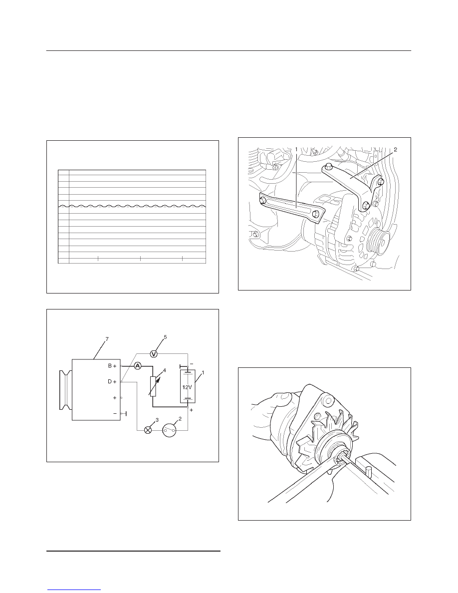
Generator Power
1. Adjust load resistor, if the required load currents are
not attained.
2. The shape of the voltage curves on oscilloscope
curve should be regular.
3. Test value: 5 to 7A.
4. If the required minimum current intensity is not
attained, or if the oscilloscope picture shows
variations, the alternator should be overhauled.
066RW018
Regulated Voltage Circuit Diagram
066RW019
Legend
(1) Battery
(2) Ignition Lock
(3) Charge Telltale
(4) Resistor, for attainment of load current with the
battery set in series
(5) Voltmeter
(6) Ammeter
(7) Generator
Installation
1. Install generator assembly and bring generator
assembly to the position to be installed.
2. Install generator bracket (1), (2) and tighten to the
specified torque.
Torque:
Long bolt: 35 N·m (26 lb ft)
Short bolt: 20 N·m (15 lb ft)
065RW025
3. Connect wiring harness connector.
4. Move drive belt tensioner to loose side using wrench,
then install drive belt to normal position.
5. Reconnect battery ground cable.
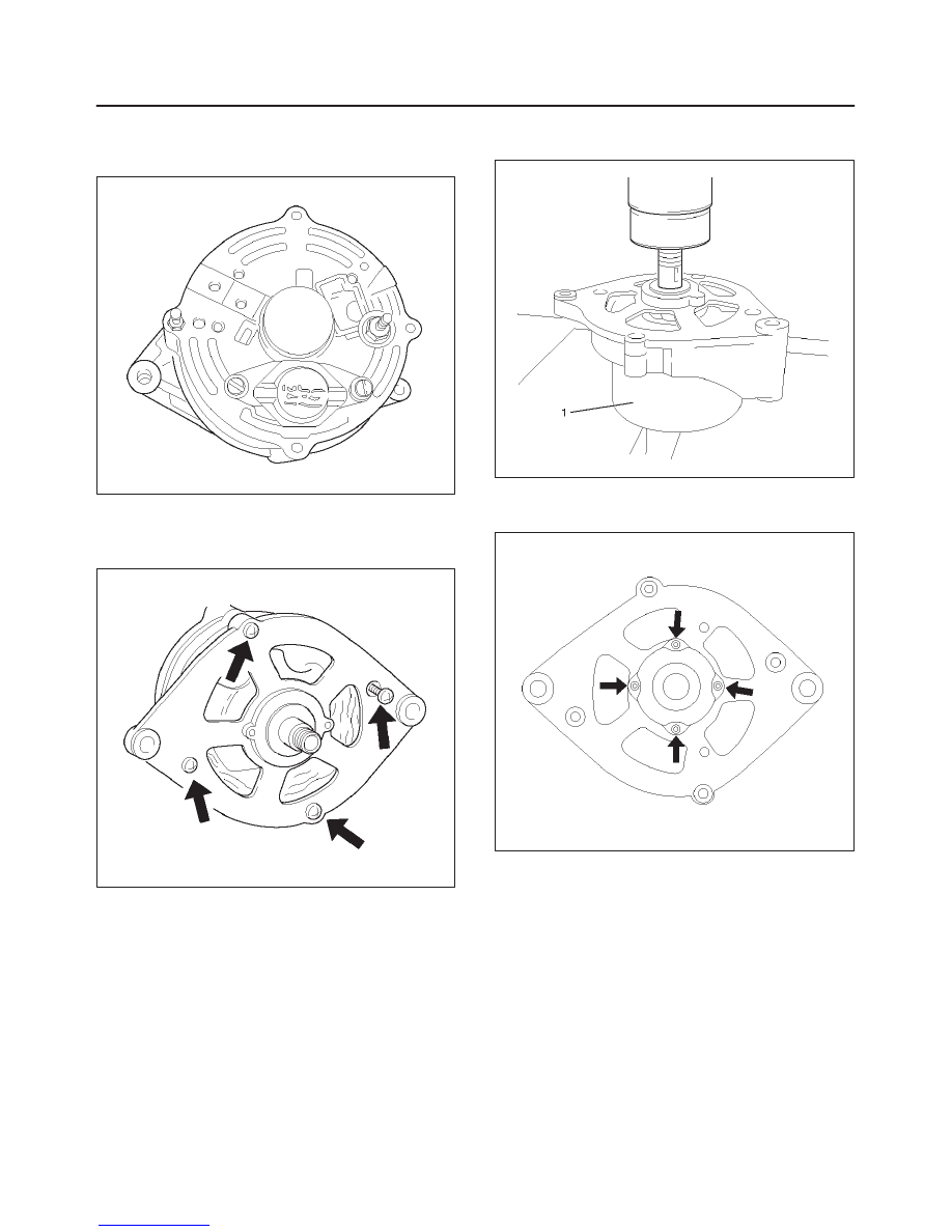
Disassembly
1. Belt pulley nut.
066RW016
6D3–10 STARTING AND CHARGING SYSTEM (X22SE 2.2L)
2. Spring ring, washer, belt pulley halves, spacing ring,
fan pinion, pulley spring.
3. Voltage regulator with brush holder.
066RW014
4. Drive bearing with clawpole armature.
5. Mark housing halves.
6. 4 fastening bolts.
066RW015
7. Clawpole armature from drive bearing.
8. Lay suitable pipe piece (1) underneath.
066RW013
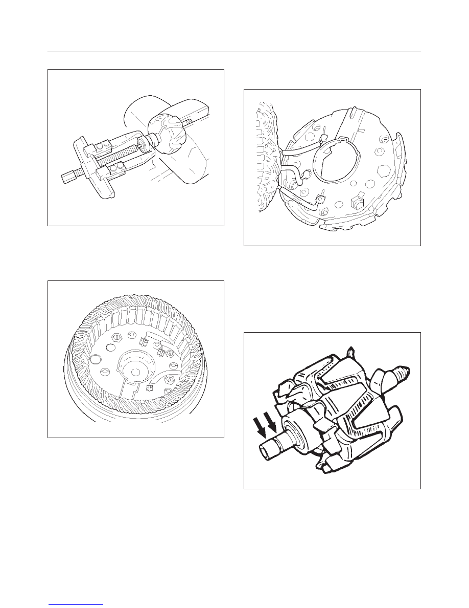
9. Bearing cover of drive bearing.
10. Ball bearing from drive bearing.
066RW017
6D3–11
STARTING AND CHARGING SYSTEM (X22SE 2.2L)
11. Ball bearing from armature shaft.
066RW012
12. Nut from connecting pins “B+” and “D+”.
13. Washers and insulating material.
14. Diode plate.
15. Remove together with stator winding from slip ring
bearing.
066RW008
16. Spray sleeve (if present).
17. Carefully bend off diode plate.
18. Unsolder stator winding from diode plate.
066RW010
Inspection and Repair
Repair or replace necessary parts if extreme wear or
damage is found during inspection.
Rotor Assembly
1. Check the rotor slip ring surfaces for contamination
and roughness. If rough, polish with #500–600
sandpaper.
066RS014
6D3–12 STARTING AND CHARGING SYSTEM (X22SE 2.2L)
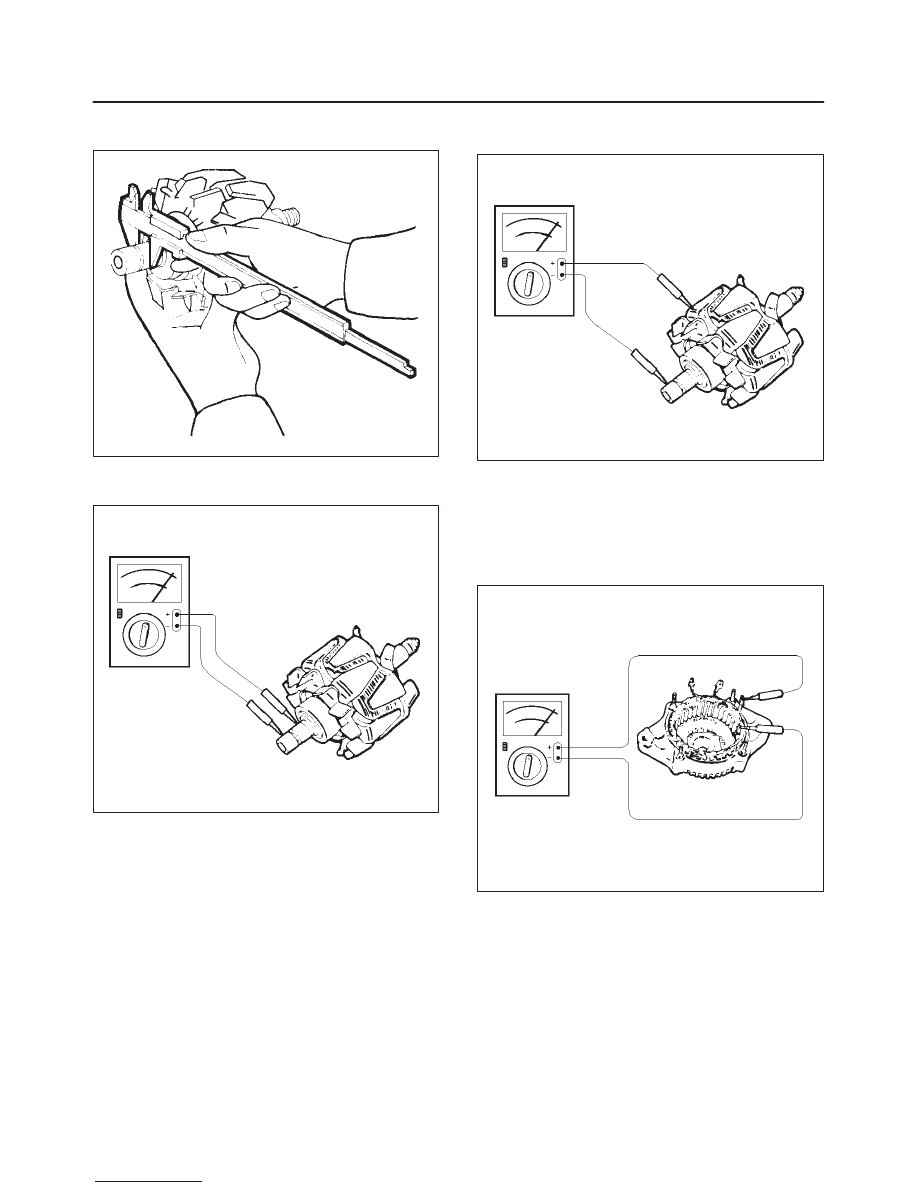
2. Measure the slip ring diameter, and replace if it
exceeds the limit.
066RS015
3. Check resistance between slip rings, and replace if
there is no continuity.
066RS016
4. Check for continuity between slip ring and rotor core.
In case of continuity, replace the rotor assembly.
066RS017
Stator Coil
1. Measure resistance between respective phases.
2. Measure insulation resistance between stator coil
and core with a mega–ohmmeter.
If less than standard, replace the coil.
066RS018
Нет комментариевНе стесняйтесь поделиться с нами вашим ценным мнением.
Текст