Isuzu Rodeo UE. Manual — part 30
2A–16 POWER–ASSISTED STEERING SYSTEM
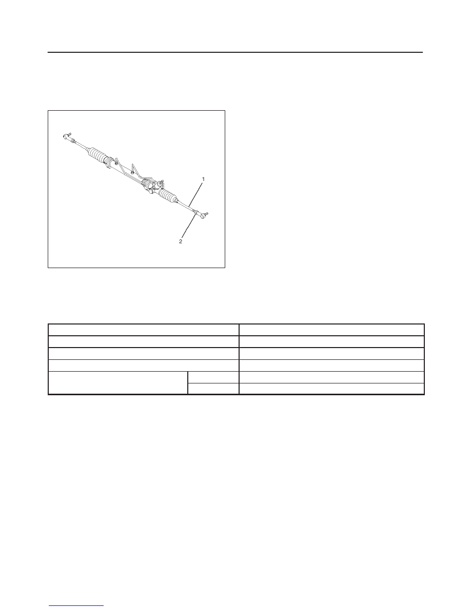
Toe-in Adjustment
1. To adjust the toe-in angle, loosen the lock nuts (2) on
the tie rod (1) and turn the tie rod. Turn both rods the
same amount, to keep the steering wheel centered .
Toe-in: 0
±
2 mm (0
±
0.08 in)
433RW003
2. Tighten the lock nut to the specified torque.
Torque: 98 N·m (72 lb ft)
Main Data and Specifications
General Specification
Caster
2
°
30’
±
1
°
Camber
0
°
±
30’
King pin inclination
12
°
30’
±
30’
Toe-in
0
±
2 mm (0
±
0.08 in)
Max. steering angle
inside
32.6
°
(+0
°
30’ to –2
°
30’ )
outside
31.8
°
POWER–ASSISTED STEERING SYSTEM
2A–17
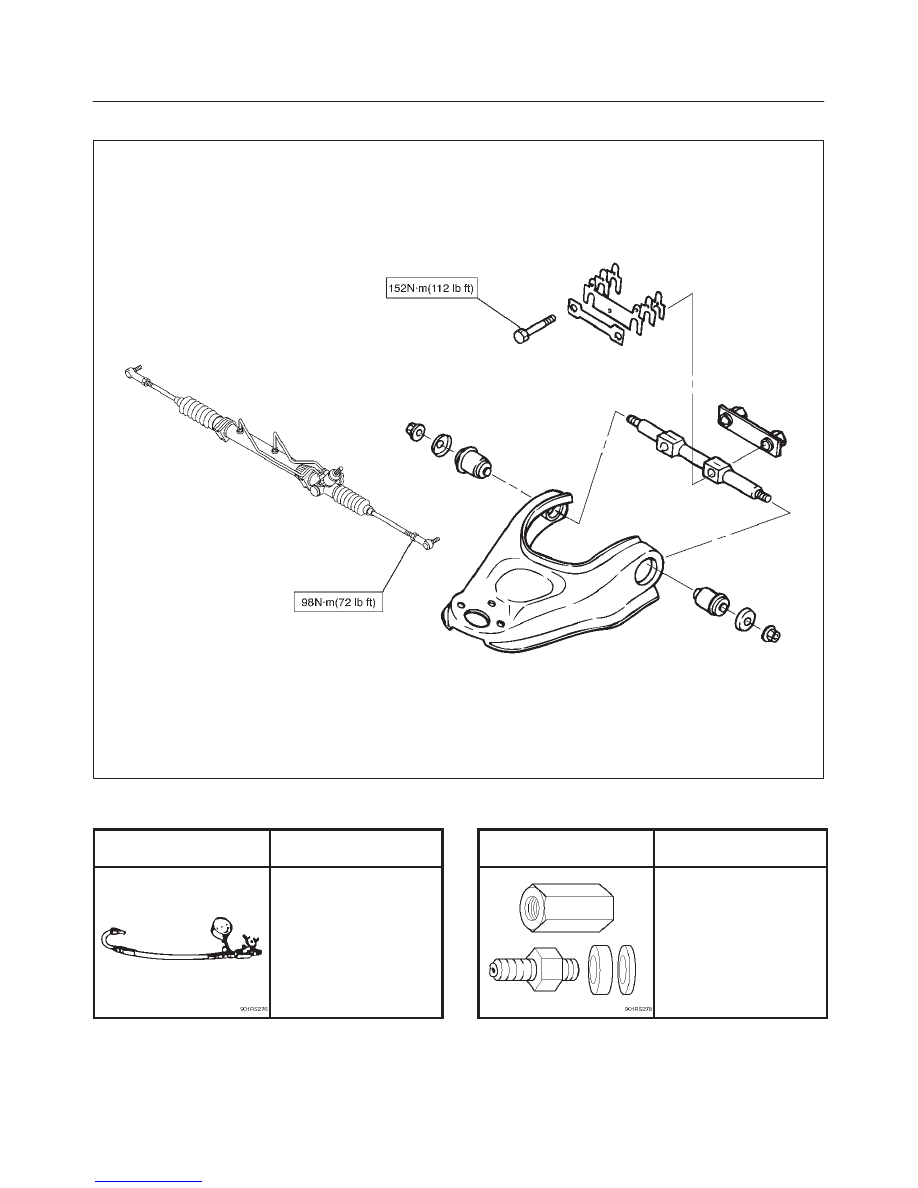
Torque Specification
E02RX001
Special Tools
ILLUSTRATION
TOOL NO.
TOOL NAME
J–29877–A
Tester;
Power steering
ILLUSTRATION
TOOL NO.
TOOL NAME
J–39213
Adapter;
Power steering tester
2A–18 POWER–ASSISTED STEERING SYSTEM
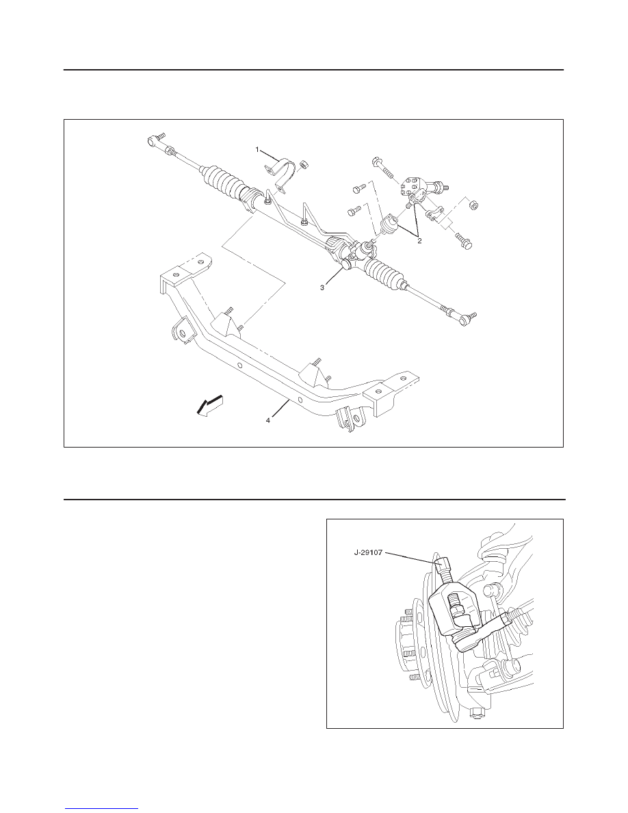
Power Steering Unit
Power Steering Unit and Associated Parts
431RW013
Legend
(1) Bracket
(2) Transfer Gear Assembly
(3) Power Steering Unit Assembly
(4) Crossmember
Removal
1. Remove the stone guard.
2. Remove the transfer gear assembly.
Make a setting mark across the coupling flange and
steering unit to ensure reassembly of the parts in the
original position.
3. Drain power steering fluid.
4. Remove the tie rod end assembly from knuckle.
Use tie rod end remover J–29107.
433RW002
POWER–ASSISTED STEERING SYSTEM
2A–19
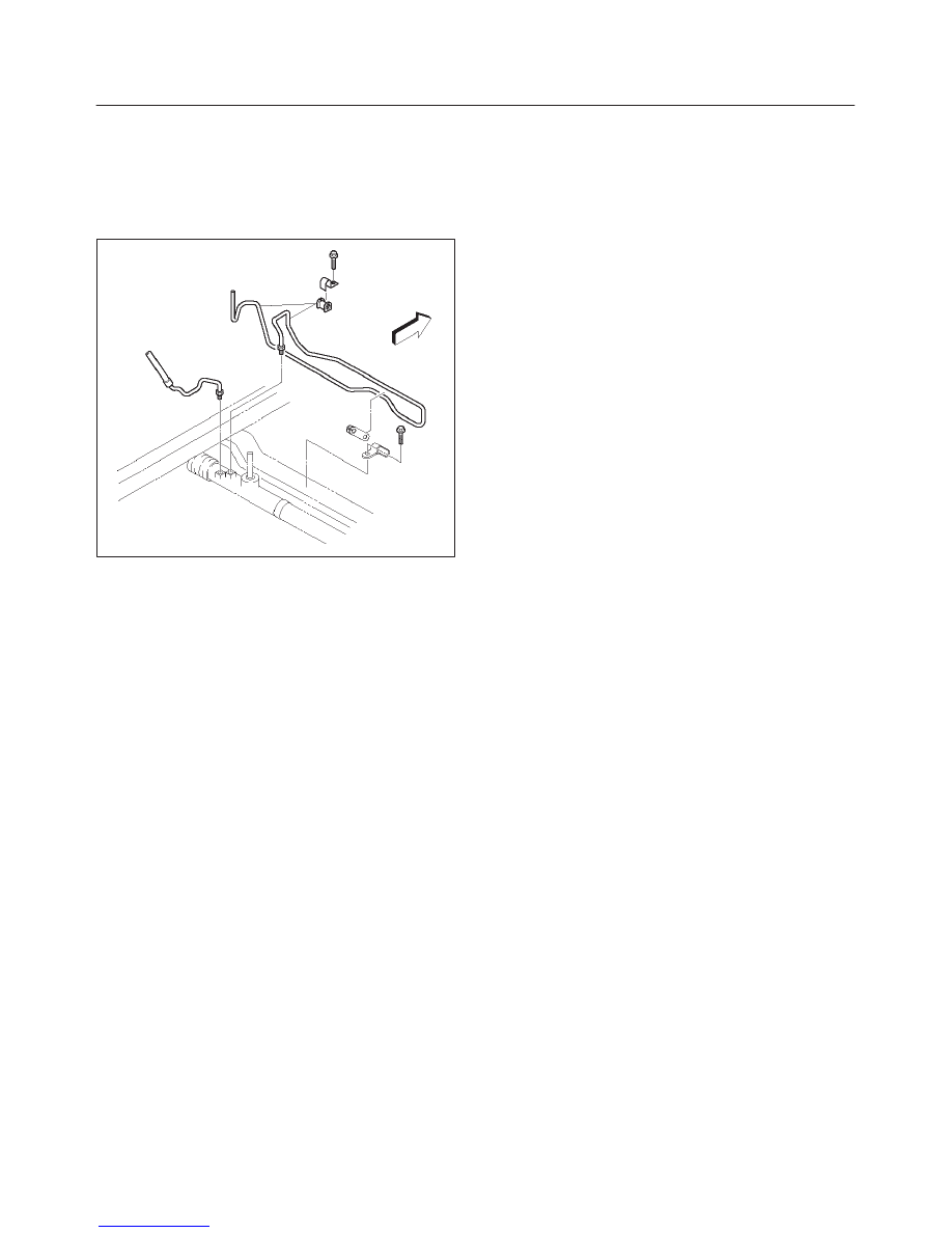
5. Disconnect the feed line and return line from steering
unit.
Remove the clips on the crossmember and frame.
Wire the power steering line to frame.
NOTE: Take care to prevent foreign matter from entry
when disconnect the power steering line.
435RW001
4
×
4 model:
1. Remove the torsion bar. Refer to Front Suspension in
Suspension section.
2. Remove the lower control arm bolt (Frame side).
Refer to Front Suspension in Suspension section.
3. Remove the crossmember fixing bolt.
4. Remove the power steering unit with the
crossmember.
5. Remove the power steering unit.
4
×
2 model:
1. Remove the power steering unit from the
crossmember.
Installation (4
×
2 Model)
1. Install power steering unit to crossmember.
Tighten fixing bolt to specified torque.
Torque: 116 N·m (85 lb ft)
2. Connect the feed line and return line.
Torque: 25 N·m (18 lb ft)
3. Install tie–rod end assembly to knuckle.
Torque: 118 N·m (87 lb ft)
4. Install transfer gear assembly.
Align the setting marks made at removal.
Torque: 31 N·m (23 lb ft)
5. Install the stone guard.
6. Bleed the system.
Refer to Bleeding the Power Steering System in this
section.
Installation (4
×
4 Model)
1. Install power steering unit to crossmember.
Tighten fixing bolt to specified torque.
Torque: 116 N·m (85 lb ft)
2. Install power steering unit with crossmember to
frame.
Tighten crossmember mounting bolt to specified
torque.
Torque: 190 N·m (140 lb ft)
3. Install lower control arm bolt.
Refer to Front Suspension in Suspension section.
4. Install torsion bar.
Refer to Front Suspension in Suspension section.
5. Connect the feed line and return line.
Torque: 25 N·m (18 lb ft)
6. Install tie–rod end assembly to knuckle.
Torque: 118 N·m (87 lb ft)
7. Install transfer gear assembly.
Align the setting marks made at removal.
Torque: 31 N·m (23 lb ft)
8. Install the stone guard.
9. Bleed the system.
Refer to Bleeding the Power Steering System in this
section.
Нет комментариевНе стесняйтесь поделиться с нами вашим ценным мнением.
Текст