Isuzu Rodeo UE. Manual — part 405

6E2–375
RODEO 6VD1 3.2L ENGINE DRIVEABILITY AND EMISSIONS
caused the DTC to be set occurs. This may assist in
diagnosing the condition.
DTC P1121 –TP Sensor Circuit Intermittent High Voltage
Step
Action
Value(s)
Yes
No
1
Was the “On-Board Diagnostic (OBD) System Check”
performed?
—
Go to
Step 2
Go to
OBD
System
Check
2
Is DTC P0123 also set?
—
Go to
DTC
P0123 first
Go to
Step 3
3
Is DTC P1111, P1115, and/or P1106 also set?
—
Go to
Step 6
Go to
Step 4
4
Check for a poor sensor ground circuit terminal
connection at the TP sensor.
Was a problem found?
—
Go to
Step 9
Go to
Step 5
5
Check the TP signal circuit between the TP sensor
connector and the PCM for an intermittent short to
voltage.
Was a problem found?
—
Go to
Step 10
Go to
Step 8
6
Check for an intermittent short to voltage on the 5 volt
reference “A” circuit between the PCM and the
following components:
f
MAP sensor
f
EGR valve
f
TP sensor
Was a problem found?
—
Go to
Step 10
Go to
Step 7
7
Check for a poor sensor ground terminal connection at
the PCM.
Was a problem found?
—
Go to
Step 9
Go to
Step 8
8
Check for an intermittent open or a faulty splice in the
sensor ground circuit.
Was a problem found? (if no, start with the diagnosis
chart for other sensors in the circuit and see if 5V
returns.)
—
Go to
Step 10
Refer to
Diagnostic
Aids
9
Replace the faulty harness connector terminal for the
sensor ground circuit.
Is the action complete?
—
Verify repair
—
10
Repair intermittent open/short circuit in wiring harness
as necessary.
Is the action complete?
—
Verify repair
—
6E2–376
RODEO 6VD1 3.2L ENGINE DRIVEABILITY AND EMISSIONS
Diagnostic Trouble Code (DTC) P1122 TP Sensor Circuit Intermittent Low
Voltage
D06RW059
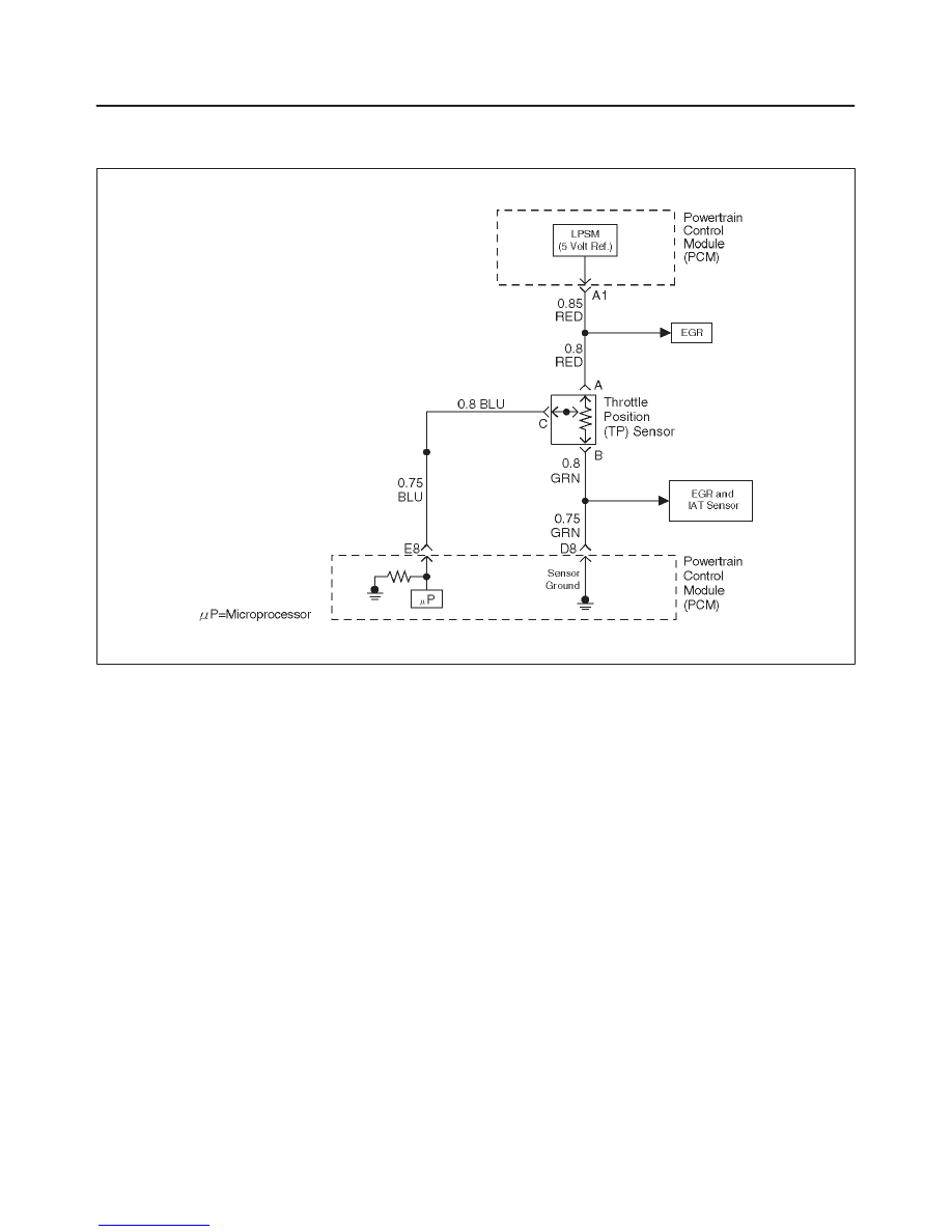
Circuit Description
The throttle position (TP) sensor circuit provides voltage
signal that changes relative to the throttle blade angle.
The signal voltage will vary from about 0.6 volts at closed
throttle to about 4.5 volts at wide open throttle (WOT).
The TP signal is one of the most important inputs used by
the powertrain control module (PCM) for fuel control and
for most of the PCM controlled outputs. If the PCM
detects a TP signal that is intermittently above the range
of the TP sensor, DTC P1121 will be set.
Conditions for Setting the DTC
f
The ignition is “ON.”
f
TP sensor indicates a throttle position signal
intermittently less than 0.22 volt for a total of 0.15
seconds over a 1.5-second period.
Action Taken When the DTC Sets
f
The PCM will not illuminate the malfunction indicator
lamp (MIL).
f
The PCM will store conditions which were present
when the DTC was set as Failure Records data only.
This information will not be stored as Freeze Frame
data.
Conditions for Clearing the MIL/DTC
f
A history DTC P1122 will clear after 40 consecutive
warm-up cycles have occurred without a fault.
f
DTC P1122 can be cleared by using the Tech 2 “Clear
Info” function or by disconnecting the PCM battery
feed.
Diagnostic Aids
Check for the following conditions:
f
Poor connection at PCM – Inspect harness connectors
for backed-out terminals, improper mating, broken
locks, improperly formed or damaged terminals, and
poor terminal-to-wire connection.
f
The TP Sensor shares a 5 Volt reference with the EGR
Valve.
If these codes are also set, it could indicate a
problem with the 5 Volt reference circuit or
components itself.
f
The TP Sensor share a ground with the EGR Valve and
the IAT Sensor.
Check the ground if these other DTCs are also
set.
f
Damaged harness – Inspect the wiring harness for
damage. If the harness appears to be OK, observe the
throttle position display on the Tech 2 while moving
connectors and wiring harnesses related to the TP
sensor. A change in the display will indicate the
location of the fault.
Reviewing the Failure Records vehicle mileage since the
diagnostic test last failed may help to determine how often
the condition that caused the DTC to be set occurs. This
may assist in diagnosing the condition.

6E2–377
RODEO 6VD1 3.2L ENGINE DRIVEABILITY AND EMISSIONS
DTC P1122 –TP Circuit Intermittent Low Voltage
Step
Action
Value(s)
Yes
No
1
Was the “On-Board Diagnostic (OBD) System Check”
performed?
—
Go to
Step 2
Go to
OBD
System
Check
2
Is DTC P0122 also set?
—
Go to
DTC
P0122 first
Go to
Step 3
3
Is DTC P1107 also set?
—
Go to
Step 6
Go to
Step 4
4
Check for a poor 5 volt reference “A” circuit or TP signal
circuit terminal connection at the TP sensor.
Was a problem found?
—
Go to
Step 9
Go to
Step 5
5
Check the TP signal circuit between the TP sensor
connector and the PCM for an intermittent open or
short to ground.
Was a problem found?
—
Go to
Step 10
Go to
Step 8
6
Check for an intermittent short to ground on the 5 volt
reference “A” circuit between the PCM and the
following components:
f
MAP sensor
f
EGR valve
f
TP sensor
Was a problem found?
—
Go to
Step 10
Go to
Step 7
7
Check for a poor 5 volt reference “A” circuit terminal
connection at the PCM.
Was a problem found?
—
Go to
Step 9
Go to
Step 8
8
Check for an intermittent open or a faulty splice in the 5
volt reference “A” circuit.
Was a problem found? (if no, start with the diagnosis
chart for other sensors in the circuit and see if 5V
returns.)
—
Go to
Step 10
Refer to
Diagnostic
Aids
9
Replace the faulty harness connector terminal(s) for
the 5 volt reference “A” circuit and/or the TP signal
circuit as necessary.
Is the action complete?
—
Repair
complete. If
a driveability
symptom still
exists, refer
to
Symptoms.
—
10
Repair the intermittent open/short circuit in wiring
harness as necessary.
Is the action complete?
—
Repair
complete. If
a driveability
symptom still
exists, refer
to
Symptoms.
—
6E2–378
RODEO 6VD1 3.2L ENGINE DRIVEABILITY AND EMISSIONS
Diagnostic Trouble Code (DTC) P1133 HO2S Insufficient Switching Bank 1
Sensor 1
D06RW060
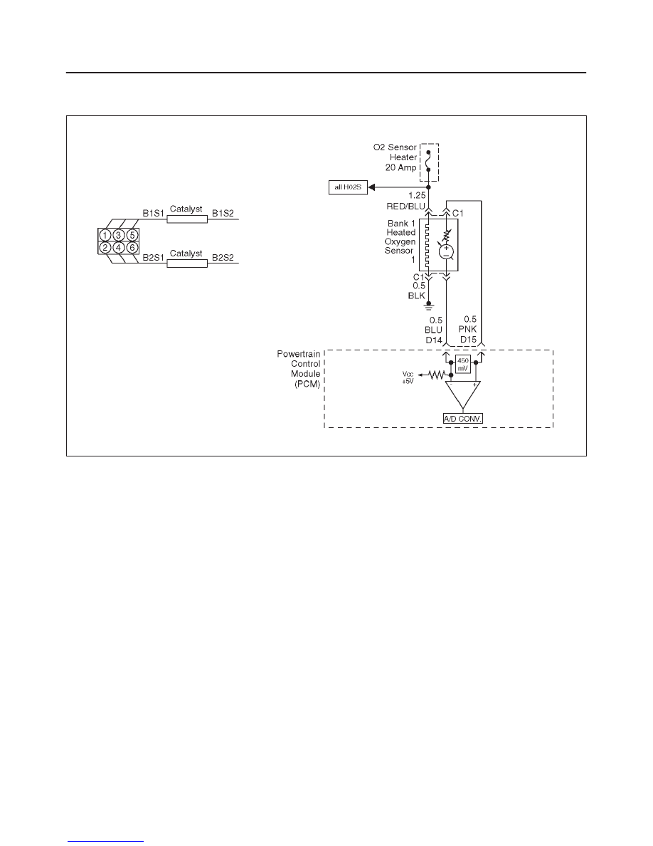
Circuit Description
The powertrain control module (PCM) monitors the
heated oxygen sensor (HO2S) activity for 90 seconds
after “closed loop” and stoichiometric operation have
been enabled. During this test period the PCM counts the
number of times that the HO2S signal voltage crosses the
rich-to-lean and lean-to-rich threshold. If the PCM
determines that the HO2S did not switch enough times,
DTC P1133 will be set.
A lean-to-rich switch is determined when the HO2S
voltage changes above and below 450 mV.
Heated oxygen sensors are used to minimize the amount
of time required for “closed loop” fuel control operation
and to allow accurate catalyst monitoring. The oxygen
sensor heater greatly decreases the amount of time
required for fuel control sensors Bank 1 HO2S 1 and Bank
2 HO2S 1 to become active. Oxygen sensor heaters are
required by post-catalyst monitor sensors to maintain a
sufficiently high temperature for accurate exhaust oxygen
content readings further from the engine.
Conditions for Setting the DTC
f
Engine coolant temperature (ECT) is above 50
°
C
(122
°
F) for automatic transmission; 75
°
C (167
°
F) for
manual transmission.
f
Engine is operating in “closed loop”.
f
The engine has been running at least one minute.
f
Canister purge duty cycle is greater than 2%.
f
Engine speed is between 1500 RPM and 3000 RPM.
f
Mass air flow (MAF) is between 9 g/second and 42
g/second.
f
Above conditions are present for 3 seconds.
f
90 seconds after “closed loop” and stoichiometric
operation have been achieved, the PCM monitors the
oxygen sensor as it switches above and below 450 mV.
If fewer than 23 rich-to-lean and lean-to-rich switches
are detected, DTC P1133 will be set.
Action Taken When the DTC Sets
f
The PCM will illuminate the malfunction indicator lamp
(MIL) after the second consecutive trip in which the
fault is detected.
f
”Open loop” fuel control will be in effect.
f
The PCM will store conditions which were present
when the DTC was set as Freeze Frame and in the
Failure Records data.
Conditions for Clearing the MIL/DTC
f
The PCM will turn the MIL “OFF” on the third
consecutive trip cycle during which the diagnostic has
been run and the fault condition is no longer present.
f
A history DTC P1133 will clear after 40 consecutive
warm-up cycles have occurred without a fault.
f
DTC P1133 can be cleared by using Tech 2 “Clear Info”
function or by disconnecting the PCM battery feed.
Нет комментариевНе стесняйтесь поделиться с нами вашим ценным мнением.
Текст