Isuzu Rodeo UE. Manual — part 606
METER AND GAUGE
8E–9
Meter Assembly W/A/T
Connector No. I–10
Terminal
Function
1
L position (A/T)
2
2 position (A/T)
3
3 position (A/T)
4
D position (A/T)
5
N position (A/T)
6
R position (A/T)
7
P position (A/T)
8
A/T shift indicator control unit
9
High–beam indicator light (–)
10
High–beam indicator light (+)
Connector No. I–9
Terminal
Function
1
Illumination (–)
2
Illumination (+)
3
—
4
—
5
—
6
Winter drive indicator light
7
Power drive indicator light
8
Cruise set indicator light
9
Fuel warning light
10
—
11
Battery (+)
12
—
Connector No. I–2
Terminal
Function
1
Turn signal indicator light (Left)
2
Turn signal indicator light (Right)
3
Ground
4
—
5
Illumination (–)
6
Tachometer
7
—
8
—
9
ABS indicator light
10
4WD indicator light
11
—
12
Speedometer
13
P.C.M (Fuel)
14
Gnd
Connector No. I–1
Terminal
Function
1
—
2
—
3
—
4
Oil pressure warning light
5
Check engine warning light
6
Check trans warning light
7
Engine coolant temperature gauge
8
Brake warning light
9
Ground (Gauge)
10
Charge warning light
11
—
12
Starter switch
13
Air bag warning light
14
A/T oil temp warning light
15
Seat belt warning light
16
Illumination (+)
8E–10 METER AND GAUGE
Removal
1. Disconnect the battery ground cable.
2. Remove the Dash Side Trim Panel –LH.
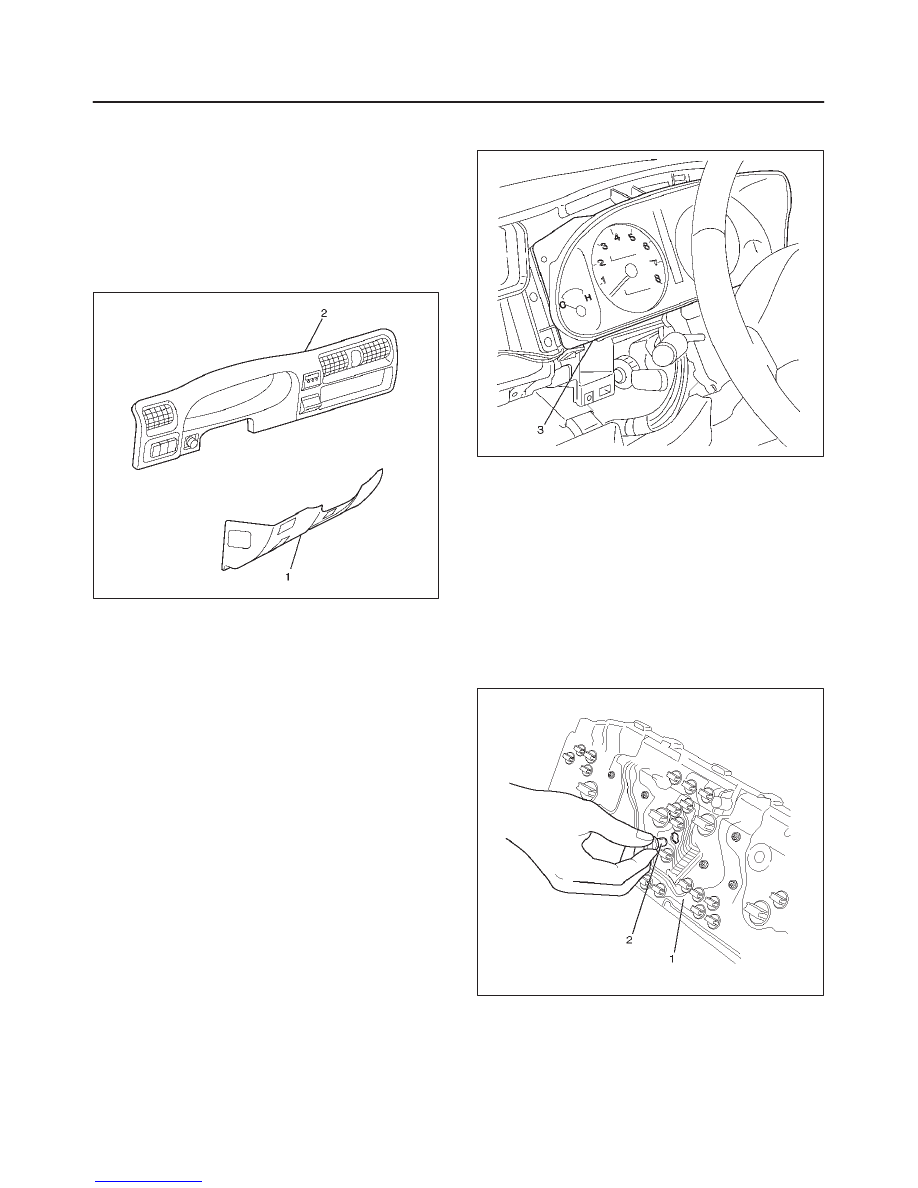
3. Remove the lower cover Assembly(1).
Refer to the Instrument Panel Assembly in Body
Structure section.
4. Remove the meter cluster Assembly(2).
Refer to the Instrument Panel Assembly in Body
Structure section.
821RW253
5. Remove four fixing screws and disconnect the meter
connectors to remove the meter assembly(3).
825RW197
CAUTION: The removed meter assembly should be
placed upright or with its face side up.
Installation
To install, follow the removal steps in the reverse order.
Warning Light Bulb, Indicator Light Bulb, Illumination Light Bulb,
A/T Indicator Light Bulb
Removal
1. Disconnect the battery ground cable.
2. Remove the meter assembly(1).
Refer to the Meter Assembly removal steps in Meter
and Gauge section.
3. Hold the bulb socket by hand and rotate it
counterclockwise to remove the socket & bulb(2)
from the meter body.
825RW059
Installation
To install, follow the removal steps in the reverse order.
METER AND GAUGE
8E–11
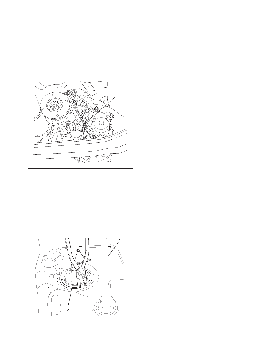
Vehicle Speed Sensor
Removal
1. Disconnect the battery ground cable.
2. Disconnect the connector, remove the vehicle speed
sensor body by rotating it and then remove the vehicle
speed sensor(1).
220RX003
Installation
To install, follow the removal steps in the reverse order,
noting the following points.
1. Tighten the vehicle speed sensor to the specified
torque.
Torque: 27 N·m (20 lb ft)
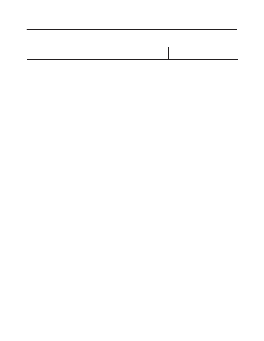
Fuel Tank Unit
Removal
1. Disconnect the battery ground cable.
2. Remove the fuel tank(1).
Refer to the Fuel Tank removal steps in Engine
section
3. Disconnect the connectors, remove five screws and
then remove the fuel tank unit(2).
825RW060
Installation
To install, follow the removal steps in the reverse order.
8E–12 METER AND GAUGE
Main Data and Specifications
Torque Specifications
Application
N·m
Lb Ft
Lb In
Vehicle Speed Sensor Fixing
27
20
—
Нет комментариевНе стесняйтесь поделиться с нами вашим ценным мнением.
Текст