Isuzu Rodeo UE. Manual — part 214

6E1–227
RODEO X22SE 2.2L ENGINE DRIVEABILITY AND EMISSION
DTC P0342 – Camshaft Position Sensor Circuit Low Input
(Cont'd)
Step
No
Yes
Value(s)
Action
10
1. Ignition ON.
2. Use a DVM to measure at the CMP connector
between the battery + and the CMP ground wire.
Does the DVM indicate the specified value?
B+
Go to Step
12
Go to Step
11
11
Repair the open ground wire.
Is the repair complete?
—
Verify repair
—
12
Use an ohmmeter to check continuity of the signal wire
between the CMP and the PCM.
Was there an open circuit?
—
Go to Step
13
Go to Step
14
13
Repair the open signal wire.
Is the action complete?
—
Verify repair
—
14
1. Ignition ON.
2. Check the signal wire for a short to ground or a short
to voltage.
Was a problem found?
—
Go to Step
15
Go to Step
16
15
Repair the signal circuit problem.
Is the action complete?
—
Verify repair
—
16
Replace the CMP Sensor.
Is the action complete?
—
Verify repair
—
6E1–228
RODEO X22SE 2.2L ENGINE DRIVEABILITY AND EMISSION
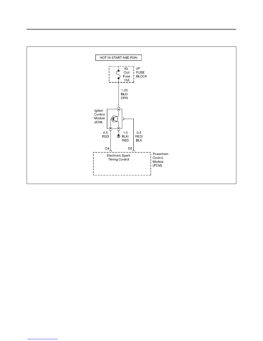
DIAGNOSTIC TROUBLE CODE (DTC) P0351 IGNITION COIL ”A” PRIMARY/
SECONDARY CIRCUIT MALFUNCTION
D06RX054
Circuit Description
The ignition control circuit provides a zero volt or a 5 volt
signal to the ignition control module. The normal circuit
voltage is zero volts. When the module receives the 5 volt
signal from the powertrain control module (PCM), it
provides a ground path for the B+ voltage supplied to the
ignition primary coil. When the PCM turns off the 5 volts to
the module, the module will remove the ground path of the
ignition primary coils; causing the magnetic field
produces a voltage in the secondary coils which fires the
spark plug.
The circuit between the PCM and the ignition control
module is monitored for an open circuit, short to voltage,
and short to ground. When the PCM detects a problem in
the ignition control circuit, it will set DTC P0351. DTC
P0351 is a type A code.
Conditions for Setting the DTC
f
Ignition ON.
f
Output voltage is not equal to 5 volts when output is
ON.
f
Output voltage is not equal to 0 volt when output is
OFF.
f
Twenty test failures within 40 samples of continuous
circuit monitoring.
Action Taken When the DTC Sets
f
The PCM will illuminate the malfunction indicator lamp
(MIL) the first time the fault is detected.
f
The PCM will store conditions which were present
when the DTC was set as Freeze Frame and in the
Failure Records data.
Conditions for Clearing the MIL/DTC
f
The PCM will turn the MIL OFF on the third consecutive
trip cycle during which the diagnostic has been run and
the fault condition is no longer present.
f
A history DTC P0351 will clear after 40 consecutive
warm–up cycles have occurred without a fault.
f
DTC P0351 can be cleared by using the Scan Tool’s
”Clear Info” function.
Diagnostic Aids
Check for the following conditions:
f
Poor connection at the PCM – Inspect the harness
connectors for backed–out terminals, improper
mating, broken locks, improperly formed or damaged
terminals, and poor terminal–to–wire connections.
f
Damaged harness – Inspect the wiring harness for
damage; Open circuits, shorts to ground, or shorts to
Voltage. If the harness appears to be OK, observe the
Tech 2 display related to DTC P0351 while moving the
connector and wiring related to the ignition system. A
change in the display will indicate the location of the
fault.
6E1–229
RODEO X22SE 2.2L ENGINE DRIVEABILITY AND EMISSION
Reviewing the Failure Records vehicle mileage since the
diagnostic test last failed may help determine how often
the condition that caused the DTC to be set occurs. This
may assist in diagnosing the condition.
DTC P0351 Ignition Coil ”A” Primary/Secondary Circuit Malfunction
Step
Action
Value(s)
Yes
No
1
Was the ”On–Board Diagnostic (OBD) System Check”
performed?
—
Go to Step 2
Go to OBD
System
Check
2
Check for a faulty connection or damaged terminals at
the ignition control module.
Was a problem found?
—
Verify Repair
Go to Step 3
3
Check for a faulty connection or damaged terminals at
the PCM connector.
Was a problem found?
—
Verify Repair
Go to Step 4
4
1. Ignition OFF.
2. Disconnect the PCM and the ignition control
module.
3. Check the ignition control circuit for a short to
voltage.
Was a problem found?
—
Verify Repair
Go to Step 5
5
Check the ignition control circuit for a short to voltage.
Was a problem found?
—
Verify Repair
Go to Step 6
6
Check for an open in the ignition control circuit.
Was a problem found?
—
Verify Repair
Go to Step 7
7
Replace the ignition control module.
Verify repair.
Is there still a problem?
—
Go to Step 8
—
8
Replace the PCM.
IMPORTANT: The replacement PCM must be
programmed. Refer to On–Vehicle Service in
Powertrain Control Module and Sensors for
procedures.
And also refer to latest Service Bulletin.
Check to see if the Latest software is released or not.
And then Down Load the LATEST PROGRAMMED
SOFTWARE to the replacement PCM.
Is the repair complete?
—
Verify Repair
—

6E1–230
RODEO X22SE 2.2L ENGINE DRIVEABILITY AND EMISSION
DIAGNOSTIC TROUBLE CODE (DTC) P0352 IGNITION COIL ”B” PRIMARY/
SECONDARY CIRCUIT MALFUNCTION
D06RX054
Circuit Description
The ignition control circuit provides a zero volt or a 5 volt
signal to the ignition control module. The normal circuit
voltage is zero volts. When the module receives the 5 volt
signal from the powertrain control module (PCM), it
provides a ground path for the B+ voltage supplied to the
ignition primary coil. When the PCM turns off the 5 volts to
the module, the module will remove the ground path of the
ignition primary coils; causing the magnetic field
produces a voltage in the secondary coils which fires the
spark plug.
The circuit between the PCM and the ignition control
module is monitored for an open circuit, short to voltage,
and short to ground. When the PCM detects a problem in
the ignition control circuit, it will set DTC P0352. DTC
P0352 is a type A code.
Conditions for Setting the DTC
f
Ignition ON.
f
Output voltage is not equal to 5 volts when output is
ON.
f
Output voltage is not equal to 0 volt when output is
OFF.
f
Twenty test failures within 40 samples of continuous
circuit monitoring.
Action Taken When the DTC Sets
f
The PCM will illuminate the malfunction indicator lamp
(MIL) the first time the fault is detected.
f
The PCM will store conditions which were present
when the DTC was set as Freeze Frame and in the
Failure Records data.
Conditions for Clearing the MIL/DTC
f
The PCM will turn the MIL OFF on the third consecutive
trip cycle during which the diagnostic has been run and
the fault condition is no longer present.
f
A history DTC P0352 will clear after 40 consecutive
warm–up cycles have occurred without a fault.
f
DTC P0352 can be cleared by using the Scan Tool’s
”Clear Info” function.
Diagnostic Aids
Check for the following conditions:
f
Poor connection at the PCM – Inspect the harness
connectors for backed–out terminals, improper
mating, broken locks, improperly formed or damaged
terminals, and poor terminal–to–wire connections.
f
Damaged harness – Inspect the wiring harness for
damage; Open circuits, shorts to ground, or shorts to
Voltage. If the harness appears to be OK, observe the
Tech 2 display related to DTC P0351 while moving the
connector and wiring related to the ignition system. A
change in the display will indicate the location of the
fault.
Нет комментариевНе стесняйтесь поделиться с нами вашим ценным мнением.
Текст