Isuzu Rodeo UE. Manual — part 583
8D–180
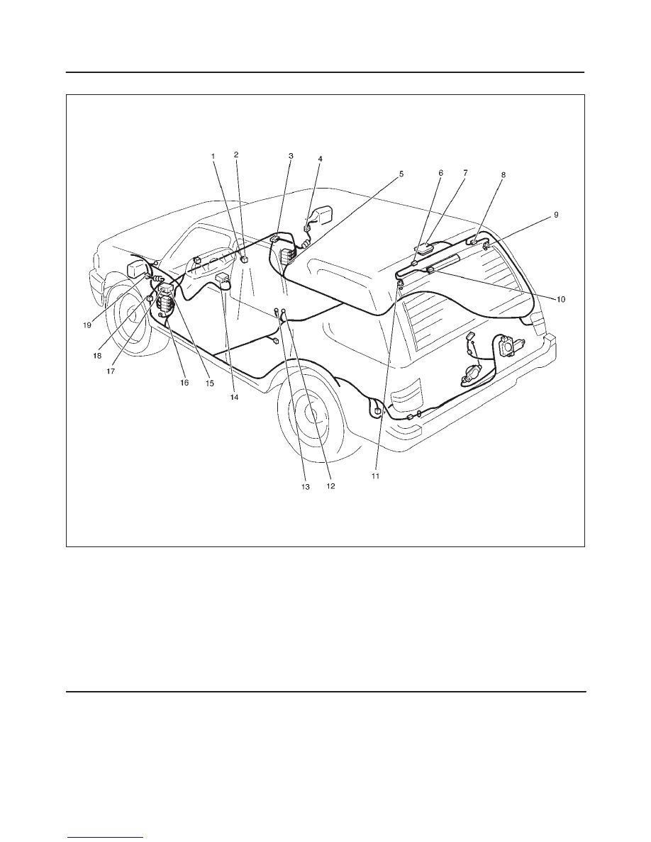
WIRING SYSTEM
Parts Location
D08RX077
Legend
(1) I–17
(2) RR Defogger Switch & Mirror Defogger Switch
(3) H–33
(4) D–12
(5) H–19
(6) H–21
(7) Luggage Room Light
(8) H–20
(9) G–9
(10) G–10, G–11
(11) G–12
(12) B–6
(13) B–8
(14) PCM
(15) Relay and Fuse Box
(16) H–31
(17) I–39 (Rear Defogger & Mirror Defogger Relay)
(18) H–28
(19) D–3

8D–181
WIRING SYSTEM
Diagnosis
Rear Defogger Does Not Operate
Step
Action
Value(s)
Yes
No
1
Are the fuse 9, 10 and 17 normal?
—
Go to Step 2
Replace the
fuse(s)
2
Are B–6 and/or B–8 grounded securely?
—
Go to Step 3
Ground it
(them)
securely
3
Remove the rear defogger relay.
Is the battery voltage applied between the rear
defogger relay harness side connector I–39 terminal 2
and the ground?
Approx. 12V
Go to Step 5
Go to Step 4
4
Repair an open circuit between the battery and
connector I–39 terminal 2.
Is the action complete?
—
Go to Step 3
—
5
Turn the starter switch on.
Is the battery voltage applied between harness side
connector I–39 terminal 4 and the ground?
Approx. 12V
Go to Step 7
Go to Step 6
6
Repair an open circuit between the fuse 17 and
connector I–39 terminal 4.
Is the action complete?
—
Go to Step 5
—
7
Disconnect the PCM connector C–1, C–2 and C–3.
Is there continuity between harness side connector
I–39 terminal 3 and harness side connector C–2
treminal C12 or connector C–1 terminal A14?
—
Go to Step 11
Go to Step 8
8
Repair an open circuit between connector I–39
terminal 3 and connector C–2 terminal C12 or
connector C–1 terminal A14.
Is the action complete?
—
Go to Step 7
—
9
Is there continuity between harness side connector
I–17 terminal 4 and connector C–3 terminal F9 or
connector C–3 terminal E12?
—
Go to Step 11
Go to Step 10
10
Repair an open circuit between connector I–17
terminal 4 and connector C–3 terminal F9 or connector
C–3 terminal E12.
Is the action complete?
—
Go to Step 9
—
11
Is there continuity between harness side connector
I–17 terminal 3 and the ground?
—
Go to Step 13
Go to Step 12
12
Repair an open circuit between connector I–17
terminal 3 and the ground B–8.
Is the action complete?
—
Go to Step 11
—
13
1. Reconnect the rear defogger relay.
2. Ground the PCM harness side connector C–2
terminal C12 or connector C–1 terminal A14.
Is the battery voltage applied between the rear
defogger harness side connector G–9 terminal 1 and
the ground?
Approx. 12V
Go to Step 14
—
14
Is there continuity between the rear defogger harness
side connector G–12 terminal 1 and the ground?
—
Go to Step 16
Go to Step 15

8D–182
WIRING SYSTEM
Step
No
Yes
Value(s)
Action
15
Repair an open circuit between connector G–12
terminal 1 and the ground B–6.
Is the action complete?
—
Go to Step 14
—
16
1. Reconnect the rear defogger switch connector
I–17.
2. Turn the rear defogger switch on.
Is the battery voltage applied between the PCM
harness side connector C–3 terminal F9 or connector
C–3 terminal E12 and the ground?
Approx. 12V
Go to Step 17
Replace the
rear defogger
switch.
17
1. Reconnect the PCM connector C–2 and C–3 or
C–1.
2. Turn the rear defogger switch on.
Is the battery voltage applied between the rear
defogger harness side connector G–9 terminal 1 and
the ground?
—
Go to Step 19
Go to Step 18
18
Replace the PCM.
Is the action complete?
—
Verify repair
—
19
Repair broken heat wire or connector poor contact of
the rear defogger.
Is the action complete?
—
Verify repair
—

8D–183
WIRING SYSTEM
Rear Defogger Timer Does Not Function
Step
Action
Value(s)
Yes
No
1
Replace the PCM.
Is the action complete?
—
Verify repair
—
Нет комментариевНе стесняйтесь поделиться с нами вашим ценным мнением.
Текст