Isuzu Rodeo UE. Manual — part 192

6E1–139
RODEO X22SE 2.2L ENGINE DRIVEABILITY AND EMISSION
f
Faulty Throttle Position sensor – With the ignition key
ON engine OFF observe the TP sensor display on the
Tech 2 while slowly depressing the accelerator to wide
open throttle. If a voltage over 4.88 volts is seen at any
point in normal accelerator travel, replace the TP
sensor.
If Diagnostic Trouble Code P0123 cannot be duplicated,
the information included in the Failure Records data can
be useful in determining vehicle mileage since the
Diagnostic Trouble Code was last set. If it is determined
that the Diagnostic Trouble Code occurs intermittently,
performing theDiagnostic Trouble Code P1121
Diagnostic Chart may isolate the cause of the fault.
Test Description
Number(s) below refer to the step number(s) on the
Diagnostic Chart:
7. Components that share the TP sensor 5 volt
reference circuit include the following devices:
f
EGR valve
f
Fuel Tank Pressure sensor
f
MAP sensor
Disconnect the component while observing the
Throttle Position sensor display on the Tech 2. If
the reading changes drastically when this
component is disconnected, replace the
component that affected the reading.
DTC P0123 – TP Sensor Circuit High Input
Step
Action
Value(s)
Yes
No
1
Was the ”On–Board Diagnostic (OBD) System Check”
performed?
—
Go to Step 2
Go to OBD
System
Check
2
1. Ignition ON, engine OFF.
2. With the throttle closed, observe the ”Throttle
Position Sensor” display on the Tech 2.
Is the ”Throttle Position Sensor” above the specified
value?
4.78 V
Go to Step 4
Go to Step 3
3
1. Ignition ON, engine OFF.
2. Review and record Tech 2 Failure Records data.
3. Operate the vehicle within Failure Records
conditions as noted.
4. Using a Tech 2, monitor “Diagnostic Trouble Code”
info for Diagnostic Trouble Code P0123.
Does the Tech 2 indicate Diagnostic Trouble Code
P0123 failed.
—
Go to Step 4
Refer to
Diagnostic
Aids
4
1. Disconnect the Throttle Position sensor electrical
connector.
2. Observe the ”Throttle Position Sensor” display on
the Tech 2.
Is the ”Throttle Position Sensor” near the specified
value? (if no, start with the diagnosis chart for other
sensors in the circuit and see if 5V returns.)
0 V
Go to Step 5
Go to Step 6
5
Probe the sensor ground circuit at the Throttle Position
sensor harness connector with a test light connected to
B+.
Is the test light ON?
—
Go to Step 7
Go to Step
10
6
1. Ignition OFF disconnect the PCM.
2. Ignition ON engine OFF.
3. Check for a short to voltage on the TP sensor signal
circuit.
4. If the TP sensor signal circuit is shorted, repair it as
necessary.
Was the TP sensor signal circuit shorted?
—
Verify repair
Go to Step
12

6E1–140
RODEO X22SE 2.2L ENGINE DRIVEABILITY AND EMISSION
DTC P0123 – TP Sensor Circuit High Input
(Cont'd)
Step
No
Yes
Value(s)
Action
7
1. Ignition ON.
2. Monitor the ”Throttle Position Sensor” Tech 2
display while disconnecting each of the
components that share the 5 volt reference circuit
(one at a time).
3. If the ”Throttle Position Sensor” Tech 2 display
changes, service the component(s) that caused the
display to change when disconnected.
Does disconnecting any of these components cause
the ”Throttle Position Sensor” display to change?
—
Verify repair
Go to Step 8
8
1. Ignition OFF disconnect the PCM.
2. Ignition ON, engine OFF.
3. Check for a short to B+ on the 5 volt reference
circuit.
4. If the 5 volt reference circuit is shorted, repair it as
necessary.
Was the 5 volt reference circuit shorted?
—
Verify repair
Go to Step 9
9
Check for poor electrical connections at the Throttle
Position sensor and replace terminals if necessary.
Did any terminals require replacement?
—
Verify repair
Go to Step
11
10
1. Ignition OFF.
2. Disconnect the PCM, and check for an open sensor
ground circuit to the Throttle Position sensor.
3. If a problem is found, repair it as necessary.
Was the sensor ground circuit to the Throttle Position
sensor open?
—
Verify repair
Go to Step
12
11
Replace the Throttle Position sensor.
Is the action complete?
—
Verify repair
—
12
Replace the PCM.
IMPORTANT: The replacement PCM must be
programmed. Refer to On–Vehicle Service in
Powertrain Control Module and Sensors for
procedures.
And also refer to latest Service Bulletin.
Check to see if the Latest software is released or not.
And then Down Load the LATEST PROGRAMMED
SOFTWARE to the replacement PCM.
Is the action complete?
—
Verify repair
—
6E1–141
RODEO X22SE 2.2L ENGINE DRIVEABILITY AND EMISSION
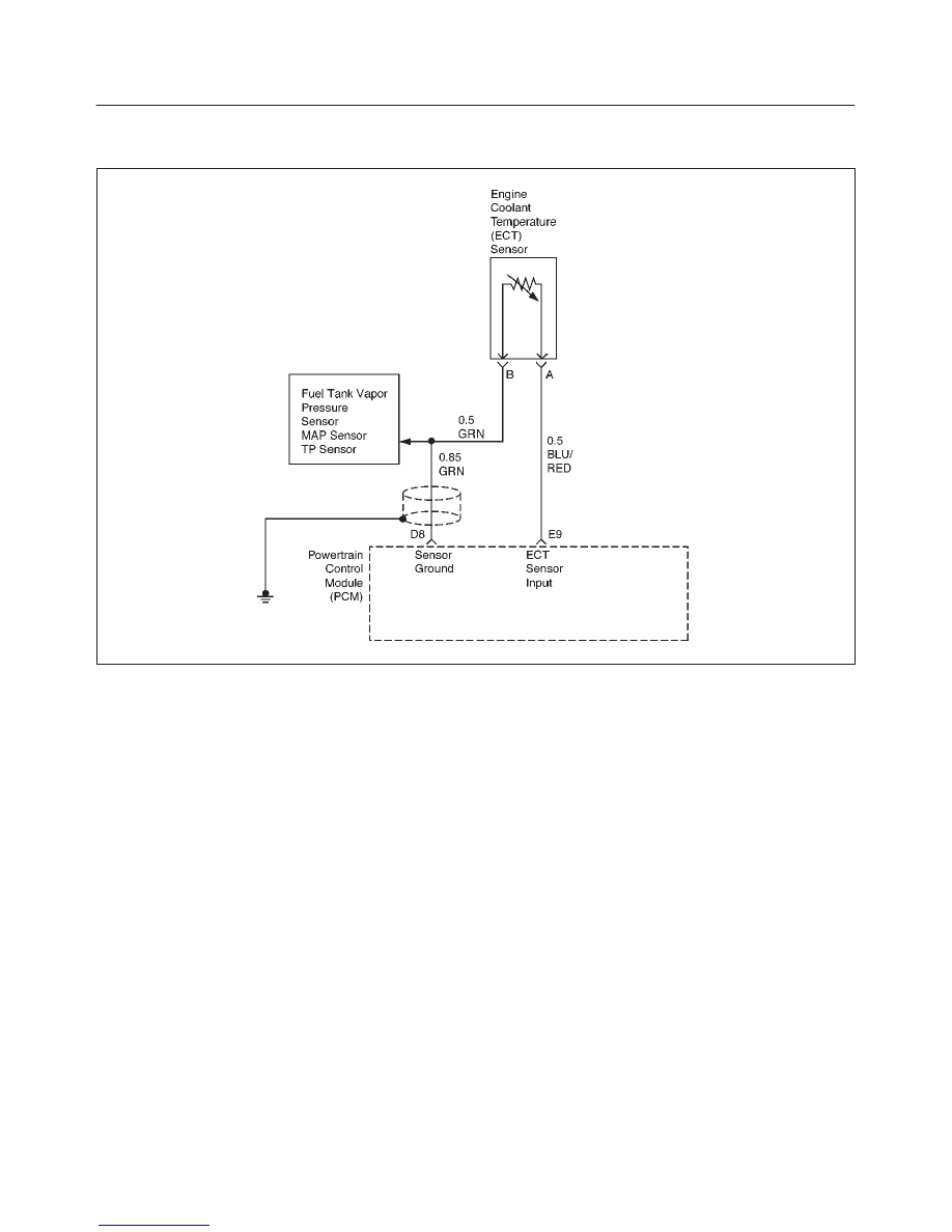
DIAGNOSTIC TROUBLE CODE (DTC) P0125 INSUFFICIENT COOLANT TEM-
PERATURE FOR CLOSED LOOP FUEL CONTROL
D06RX044
Circuit Description
To provide the best possible combination of driveability,
fuel economy, and emission control, a ”Closed Loop”
air/fuel metering system is used. When the vehicle is first
started, the powertrain control module (PCM) controls
fuel delivery in ”Open Loop” ignoring the heated oxygen
sensor (HO2S) signals and calculating air/fuel ratio based
on inputs from the engine coolant temperature, throttle
position, and mass air flow sensors.
If the PCM detects that the ECT sensor has not reached a
sufficient reading to achieve ”Closed Loop” within a
specified amount of time, DTC P0125 will set. DTC
P0125 is a type B code.
Conditions for Setting the DTC
f
No MAP, IAT, ECT, TP, Misfire, Injector, or VSS DTC
codes set.
All the above mentioned conditions are true and any
combination of the following three tests fail three times in
two consecutive ignition cycles (for a total of six failures):
Warm Case Test
f
Start–up ECT value is less than 29
°
C (84
°
F).
f
IAT is greater than 10
°
C (50
°
F).
f
Accumulated airflow is greater than 1500 grams.
f
Engine run time is greater than 90 seconds.
f
Time for coolant to reach stabilized ”Closed Loop”
value is less than 120 seconds.
Cold Case Test
f
IAT is between –7
°
C (20
°
F) and 10
°
C (50
°
F)
f
Accumulated airflow is greater than 2000 grams.
f
Engine run time is less than 225 seconds.
f
Time for coolant to reach stabilized ”Closed Loop”
value is less than 300 seconds.
Other Case Test
f
IAT is between –30
°
C (–22
°
F) and –7
°
C (20
°
F).
f
Accumulated airflow is greater than 3600 grams.
f
Engine run time is less than 450 seconds.
f
Time for coolant to reach stabilized ”Closed Loop”
value is less than 600 seconds.
Action Taken When the DTC Sets
f
The PCM will illuminate the malfunction indicator lamp
(MIL) after the second consecutive trip in which the
fault is detected.
f
The PCM will store conditions which were present
when the Diagnostic Trouble Code was set as Freeze
Frame and in the Failure Records data.
Conditions for Clearing the MIL/DTC
f
The PCM will turn the MIL OFF on the third consecutive
trip cycle during which the diagnostic has been run and
the fault condition is no longer present.
6E1–142
RODEO X22SE 2.2L ENGINE DRIVEABILITY AND EMISSION
f
A history Diagnostic Trouble Code P0125 will clear
after 40 consecutive warm–up cycles have occurred
without a fault.
f
Diagnostic Trouble Code P0125 can be cleared by
using the Scan Tool’s ”Clear Info” function.
Diagnostic Aids
DTC P0125 set indicates a faulty ECT sensor. Comparing
the engine coolant temperature displayed on a Tech 2
with actual coolant temperature measured with a
thermometer may isolate this condition. If the displayed
engine coolant temperature is not close to the actual
coolant temperature, replace the ECT sensor.
Check for the following conditions:
f
Poor connection at PCM – Inspect harness connectors
for back–out terminals, improper mating, broken locks,
improperly formed or damaged terminals, and poor
terminal–to–wire connection.
f
Damaged Harness – Inspect the wiring harness for
damage; open circuits, shorts to ground, or shorts to
voltage. If the harness appears to be OK, observe the
display on the Tech 2 while moving connectors and
wiring harnesses related to the sensor. A change in the
display will indicate the location of the fault.
If DTC P0125 cannot be duplicated, the information
included in the Failure Records data can be useful in
determining vehicle mileage since the DTC was last set.
Test Description
Number(s) below refer to the step number(s) on the
Diagnostic Chart:
2. Comparing the engine coolant temperature
displayed on a Tech 2 with actual coolant
temperature measured with a thermometer may
isolate this condition. If the displayed engine coolant
temperature is not close to the actual coolant
temperature, replace the ECT sensor. If the
temperatures are closed, the fault is intermittent;
refer to Diagnostic Aids.
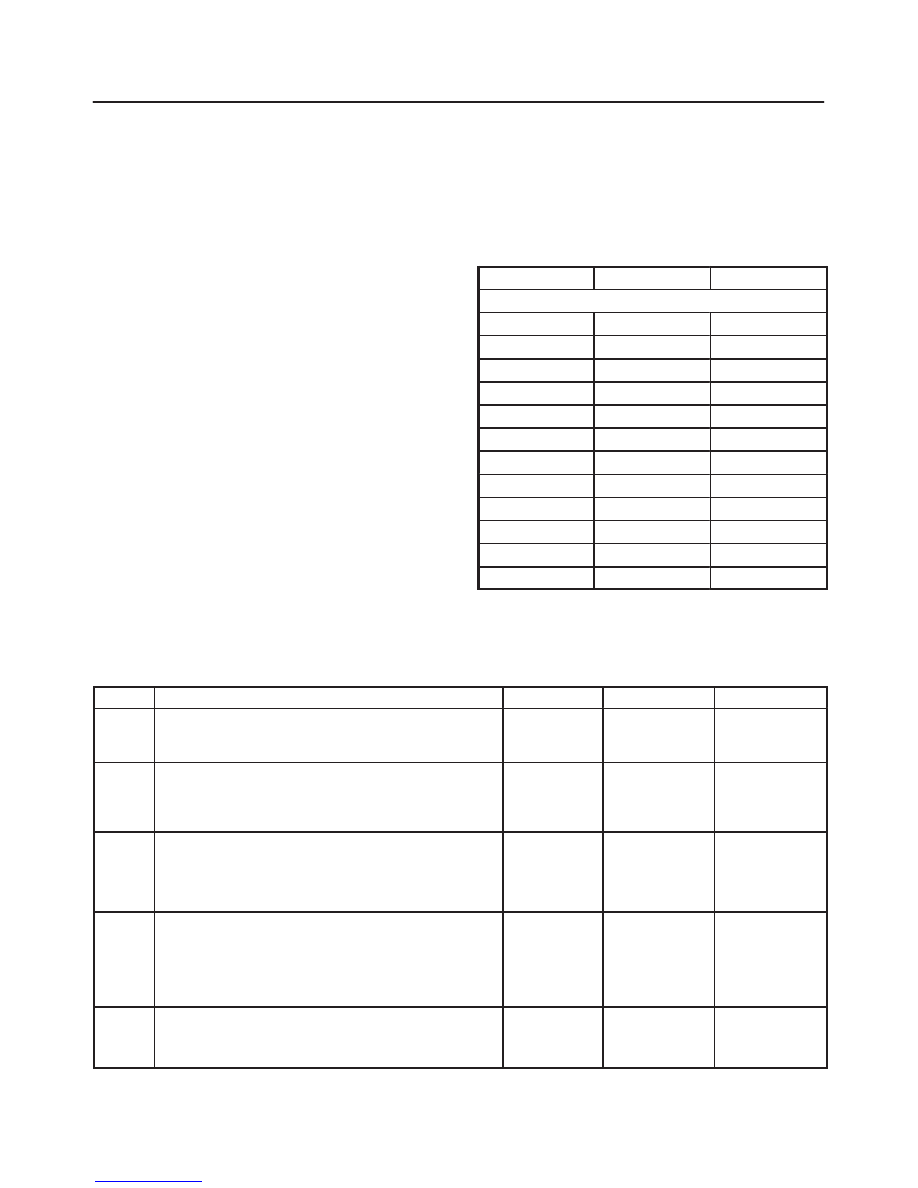
7. Engine Coolant Temperature
°
C
°
F
OHMS
Temperature vs. Resistance Values (approximate)
100
212
177
80
176
332
60
140
667
45
113
1188
35
95
1802
25
77
2796
15
59
4450
5
41
7280
–5
23
12300
–15
5
21450
–30
–22
52700
–40
–40
100700
DTC P0125 Insufficient Coolant Temperature for Closed Loop Fuel Control
Step
Action
Value(s)
Yes
No
1
Was the ”On–Board Diagnostic (OBD) System Check”
performed?
—
Go to Step 2
Go to OBD
System
Check
2
Are any ECT sensor DTC’s set?
—
Go to
applicable
ECT sensor
DTC chart
Go to Step 3
3
1. Allow the engine to cool completely.
2. Check the cooling system coolant level (refer to
Cooling and Radiator).
Is the coolant level OK?
—
Go to Step 4
Go to Step 9
4
1. Start the engine.
2. With the engine idling, monitor ”ENG COOL TEMP”
display on the Tech 2.
Does ”ENG COOL TEMP” increase to above the
specified value within 2 minutes?
21
°
C (70
°
F)
Refer to
Diagnsotic
Aids
Go to Step 5
5
Check for proper operation of the thermostat (refer to
Cooling and Radiator).
Is the thermostat operating correctly?
—
Go to Step 6
Go to Step 9
Нет комментариевНе стесняйтесь поделиться с нами вашим ценным мнением.
Текст