Isuzu KB P190. Manual — part 918
Powertrain Interface Module – V6
Page 6E1–11
2.2 Interior
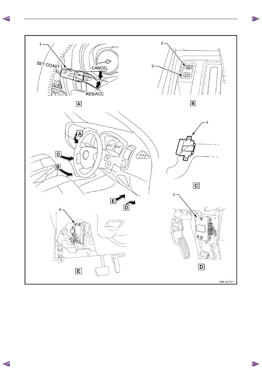
Figure 6E1 – 4
Legend
1
Cruise Control Switch Assembly
2
Power Mode Switch – Automatic Transmission
3 3
rd
Start Switch – Automatic Transmission
4
Immobiliser Control Unit (ICU)
5
Powertrain Interface Module (PIM)
6
Transmission Control Module (TCM)
N O T E
Components shown in Figure 6E1 – 4 will vary
depending on vehicle options.
Powertrain Interface Module – V6
Page 6E1–12
3
Component Description and
Operation
3.1
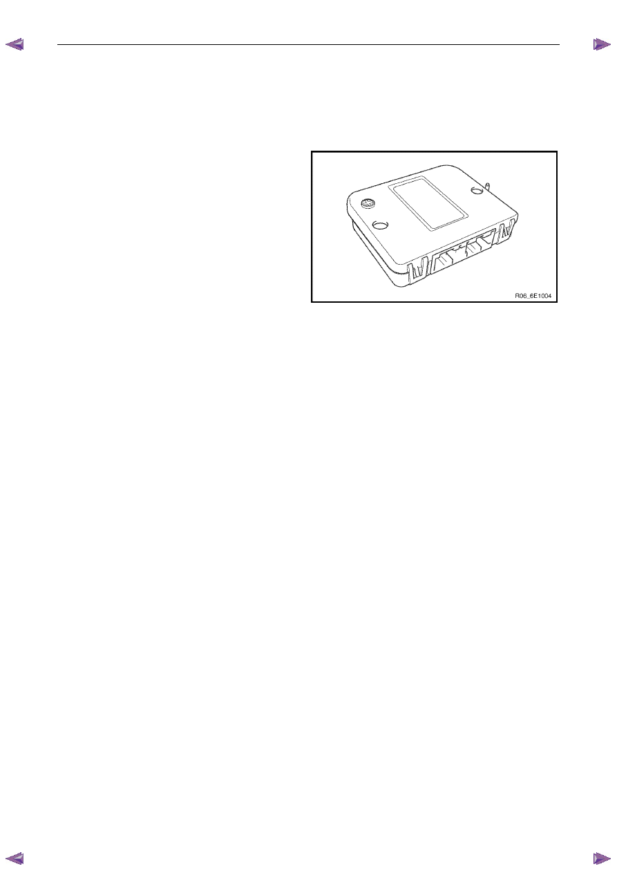
Powertrain Interface Module
The powertrain interface module (PIM) is located behind the
right-hand lower hinge pillar trim.
Figure 6E1 – 5
The PIM performs the following functions:
•
The PIM acts as the communication gateway between the GM LAN communications protocol and keyword 2000
protocol.
•
The PIM converts analogue signals from the cruise control switches into digital serial data.
•
The PIM upon inputs received from the engine control module (ECM), transmission control module (TCM) and
immobiliser control unit (ICU) controls the operation of the following instruments and warning lamps:
•
Speedometer
•
Tachometer
•
Check Transmission Lamp
•
3
rd
Gear Start Lamp
•
Power Mode Switch Lamp
•
Automatic Transmission Oil Temp Lamp
•
Cruise Set Lamp
•
Oil Pressure Lamp
•
Service Vehicle Soon (SVS) Lamp
•
Charge Warning Lamp
•
PRNDL Lamps
•
The PIM is responsible for authenticating the immobiliser control unit (ICU) prior to the engine control module
(ECM) authenticating the PIM. If any of these authentication processes fail, the vehicle will not start. For further
information on the immobiliser system, refer to 11A Immobiliser System.

Powertrain Interface Module – V6
Page 6E1–13
3.2
Powertrain Interface Module Gateway
Components
Engine Control Module
The ECM is located at the right front of the engine
assembly.
The ECM communicates directly with the transmission
control module (TCM) and PIM via the serial data network.
The ECM is also an integral part of the vehicle security
system. For further information on vehicle security, refer to
11A Immobiliser System.
Figure 6E1 – 6
Immobiliser Control Unit
The immobiliser control unit (ICU) is mounted to the left of
the steering column.
The ICU in conjunction with the, powertrain interface module
(PIM) and engine control module (ECM) immobilises the
engine. The ICU communicates with the ECM via the PIM.
Refer to 11A Immobiliser for further information on the
immobiliser system.
Figure 6E1 – 7
Automatic Transmission Control Module
The transmission control module (TCM) is located under the
right-hand rear drivers seat, beneath the carpet.
The TCM's primary role is to efficiently control transmission
shift points according to current driving and vehicle
operating conditions. To effectively do this, the TCM
requires information from other vehicle systems such as the
engine management and automatic transmission systems.
This information exchanged is achieved by connecting the
various system control modules via the serial data network.
For further information on the serial data network, refer to
1 General
Information.
Figure 6E1 – 8

Powertrain Interface Module – V6
Page 6E1–14
3.3
Powertrain Interface Module Direct Input
Switches
The following switches are direct wired to the PIM. These switches use the PIM to convert their input signals into serial
data, which is then used by the various vehicle control modules to perform varying functions.
Cruise Control Switch
The cruise control switch is located on the left-hand side of
the steering column.
The switch is comprised of three momentary contact
switches which control the following functions:
•
cruise control push button switch (ON–OFF),
•
cruise control resume – accelerate (RES–ACCEL),
and
•
cruise control set – decelerate (SET–DECEL).
The three cruise control switches directly input into the PIM.
When any of these switches are activated, the PIM sends a
message on the serial data bus to the ECM. For further
information on the cruise control system, refer to 8C Cruise
Control – HFV6.
Figure 6E1 – 9
Power Mode Switch – Automatic Transmission
The power mode switch is located at the front of the floor
console, forwards of the 3
rd
start switch.
The power mode switch is an on-off rocker type switch that
changes the transmission shift points. The power mode
switch inputs directly into the PIM. When the switch is in the
on position, the PIM sends a message on the serial data
bus to the Transmission Control Module (TCM). For further
information on the automatic transmission, refer to:
7C1 Automatic Transmission – 4L60E – General
Information.
Figure 6E1 – 10
3
rd
Start Switch – Automatic Transmission
The 3
rd
start switch is located at the front of the floor
console, behind the power mode switch.
The 3
rd
start switch is a momentary contact switch that
enables the vehicle to be driven from the stationery position
in 3
rd
. The 3
rd
start switch inputs directly into the PIM. When
the switch is pressed, the PIM sends a message on the
serial data bus to the transmission control module (TCM).
For further information on the automatic transmission, refer
to 7C1 Automatic Transmission – 4L60E – General
Information.
Figure 6E1 – 11
Нет комментариевНе стесняйтесь поделиться с нами вашим ценным мнением.
Текст