Isuzu KB P190. Manual — part 815
Engine Management – V6 – General Information
Page 6C1-1–18
3.12 Immobiliser
System
The vehicle incorporates an immobiliser system. After the ignition switch is turned to the ON position, and the powertrain
interface module (PIM) has authenticated the immobiliser control unit (ICU), the PIM sends an encrypted security code to
the engine control module (ECM). The ECM compares the received security code with its own security code, and if it is
valid, the ECM enables the vehicle to be started. For further information and diagnosis of the immobiliser system, refer to
11A Immobiliser.
For further information on the PIM, refer to 6E1 Powertrain Interface Module – V6.
Engine Management – V6 – General Information
Page 6C1-1–19
4
Component Description and
Operation
4.1
A/C Refrigerant Pressure Sensor
The engine control module (ECM) applies a positive 5 V reference voltage and ground to the air-conditioner (A/C)
refrigerant pressure sensor. The A/C refrigerant pressure sensor provides signal voltage to the ECM that is proportional
to the A/C refrigerant pressure. The ECM monitors the A/C refrigerant pressure sensor signal voltage to determine the
refrigerant pressure.
•
The A/C refrigerant pressure sensor voltage increases as the refrigerant pressure increases.
•
When the ECM detects the refrigerant pressure exceeds a predetermined value, the ECM activates the cooling
fans to reduce the refrigerant pressure.
•
When the ECM detects the refrigerant pressure is too high or too low, the ECM disables the A/C clutch to protect
the A/C compressor from damage.
4.2
Brake Pedal Switch Assembly
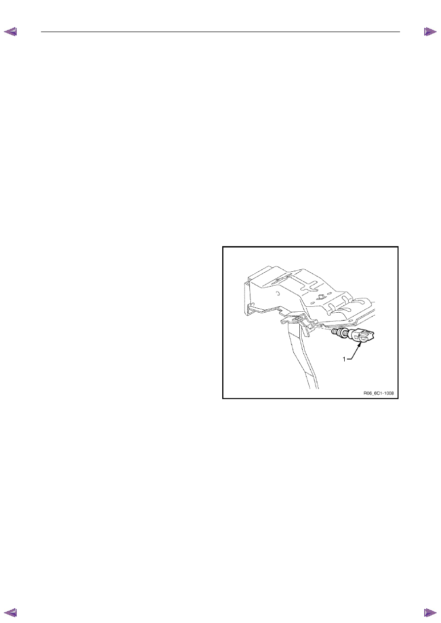
Stop Lamp and Initial Brake Apply Switch
The stop lamp and initial brake apply switch assembly (1) is
located on the brake pedal support.
The engine control module (ECM) uses the brake pedal
switch inputs to determine when the brake pedal is
depressed.
The ECM uses the two break pedal switch inputs for:-
•
Enabling cruise control,
•
Brake torque management,
•
Cross referencing the stop lamp switch against the
initial brake apply switch for correct operation.
For further information on brake torque management,
refer to 3.7
Brake Torque
Management.
For further information on the cruise control system, refer to
3.6
Cruise Control System.
Figure 6C1-1 – 13
Stop Lamp Switch
The stop lamp switch contacts are normally open with the brake pedal at rest and closed when the brake pedal is
depressed.
Initial Brake Apply Switch
The initial brake apply switch contacts are normally closed with the brake pedal at rest and open when the brake pedal is
depressed.
Engine Management – V6 – General Information
Page 6C1-1–20
4.3
Barometric Pressure Sensor
The barometric pressure (BARO) sensor measures
barometric (atmospheric) pressure. The ECM uses this
signal to make corrections to the operating parameters of
the system based on changes in air density, since the
oxygen content of atmospheric air varies proportionally to air
density (barometric / atmospheric pressure). Barometric
pressure is affected mainly by altitude and climate.
The BARO sensor provides a voltage signal to the ECM that
is a function of barometric pressure. It does this through a
series of deformation resistors, which change resistance
when a mechanical force is applied. This force is applied to
the resistors by a diaphragm on which the atmospheric
pressure acts.
The ECM supplies the BARO sensor with a 5 V reference
and a ground circuit.
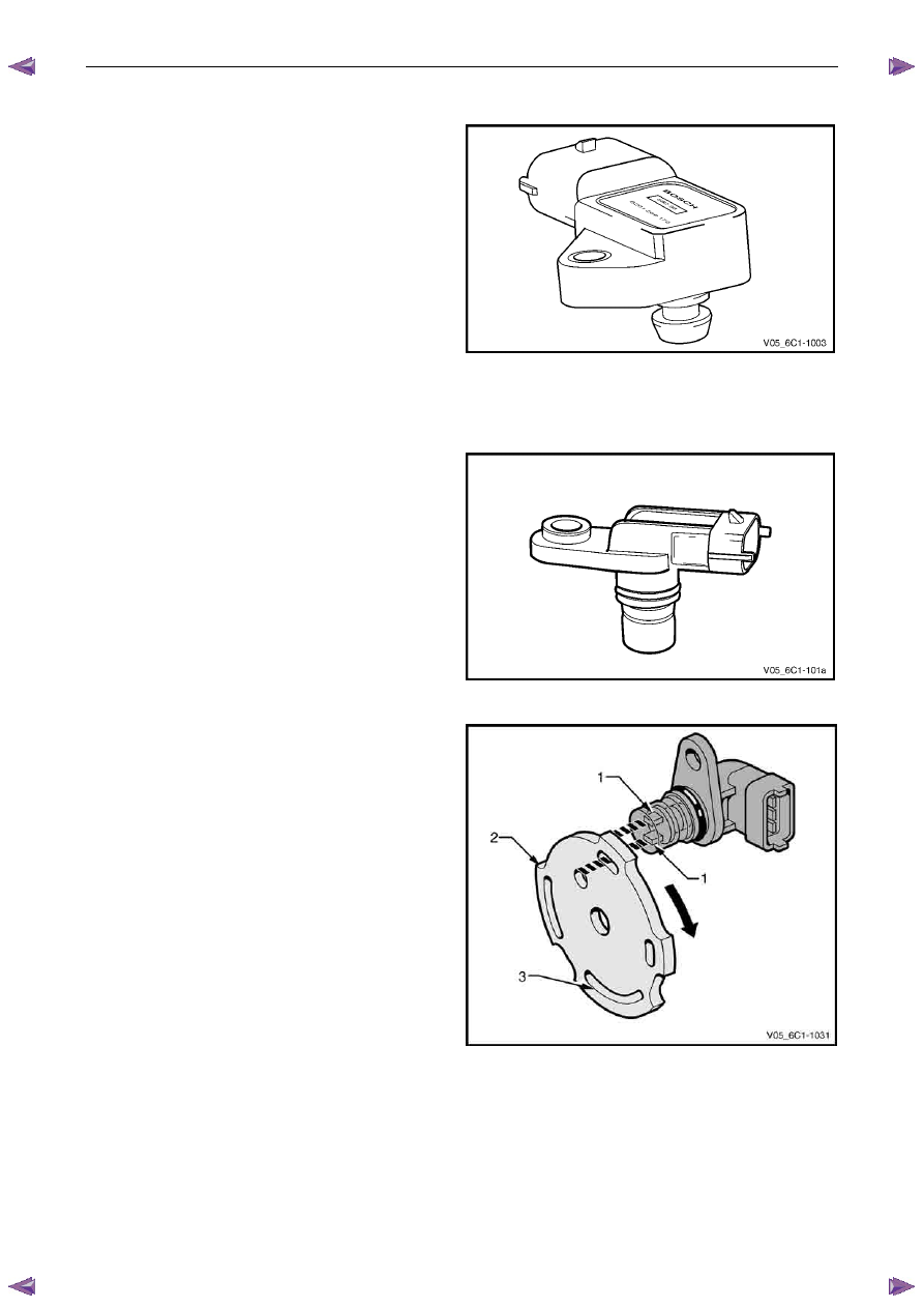
Figure 6C1-1 – 14
4.4
Camshaft Position Sensor
The HFV6 engine is fitted with an inlet camshaft position
(CMP) sensor.
The CMP sensor is used by the ECM to determine the
position of the camshafts. In conjunction with the crankshaft
position sensor, the CMP enables the ECM to determine
engine rotational position.
Figure 6C1-1 – 15
The CMP sensor operates on the dual-Hall sensing
principle. The sensor contains two hall elements (1) which
operate in conjunction with a two-track trigger wheel (2)
mounted on the camshaft.
As the tracks (3) on the trigger wheel pass the elements,
magnetic flux affects a voltage in the Hall elements. The
integrated circuit inside the sensor conditions the signal
generated by the Hall elements to provide a rectangular
wave on / off signal to the ECM.
The ECM supplies the CMP sensors with a 5 V reference
and ground circuit.
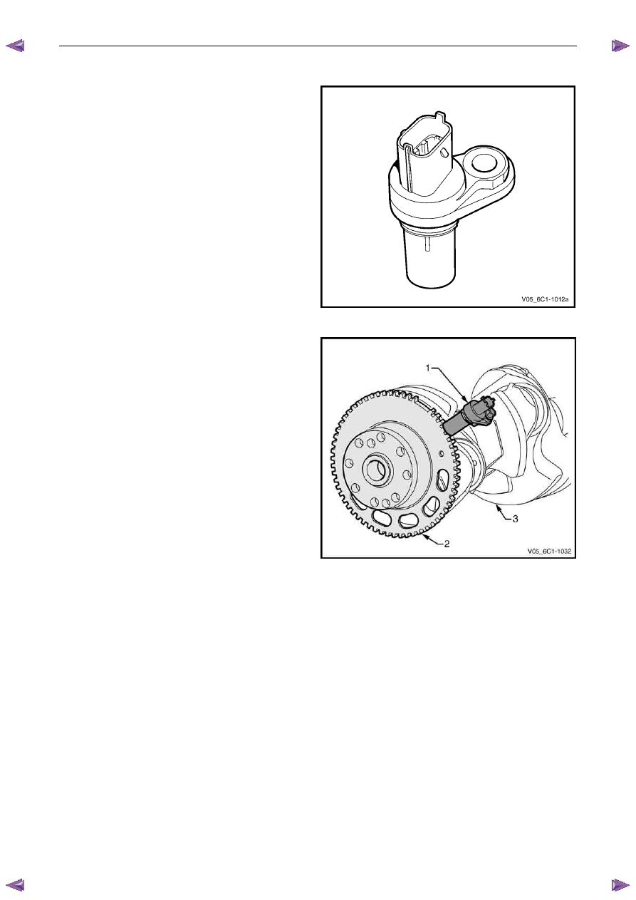
Figure 6C1-1 – 16
Engine Management – V6 – General Information
Page 6C1-1–21
4.5
Crankshaft Position Sensor
In conjunction with the camshaft position sensor, the
crankshaft position (CKP) sensor enables the ECM to
determine engine rotational position. The CKP is also used
to determine engine speed (rpm).
Figure 6C1-1 – 17
The CKP sensor (1) operates on the variable reluctance
(pulse generator) sensing principle. It contains a magnet
and pickup coil and is used in conjunction with a 58 tooth
ferromagnetic reluctor wheel (2) attached to the
crankshaft (3).
As the crankshaft rotates, the reluctor wheel revolves past
the CKP, causing fluctuations in the magnetic field inside
the sensor. This action creates an AC voltage across the
pickup coil which is processed by the ECM. An increase in
engine speed will increase the output voltage and
frequency.
The reluctor wheel teeth are placed six degrees apart.
Having only 58 teeth leaves a 12 degree open span, which
creates a signature pattern that enables the ECM to
determine the crankshaft position. The ECM determines
which two cylinders are approaching the top dead centre
based on the crankshaft position sensor signal. The CMP
sensor signals are used by the ECM to determine which
cylinder is on the firing stroke.
Figure 6C1-1 – 18
Нет комментариевНе стесняйтесь поделиться с нами вашим ценным мнением.
Текст