Isuzu KB P190. Manual — part 650
Engine Mechanical – V6
Page 6A1–121
34
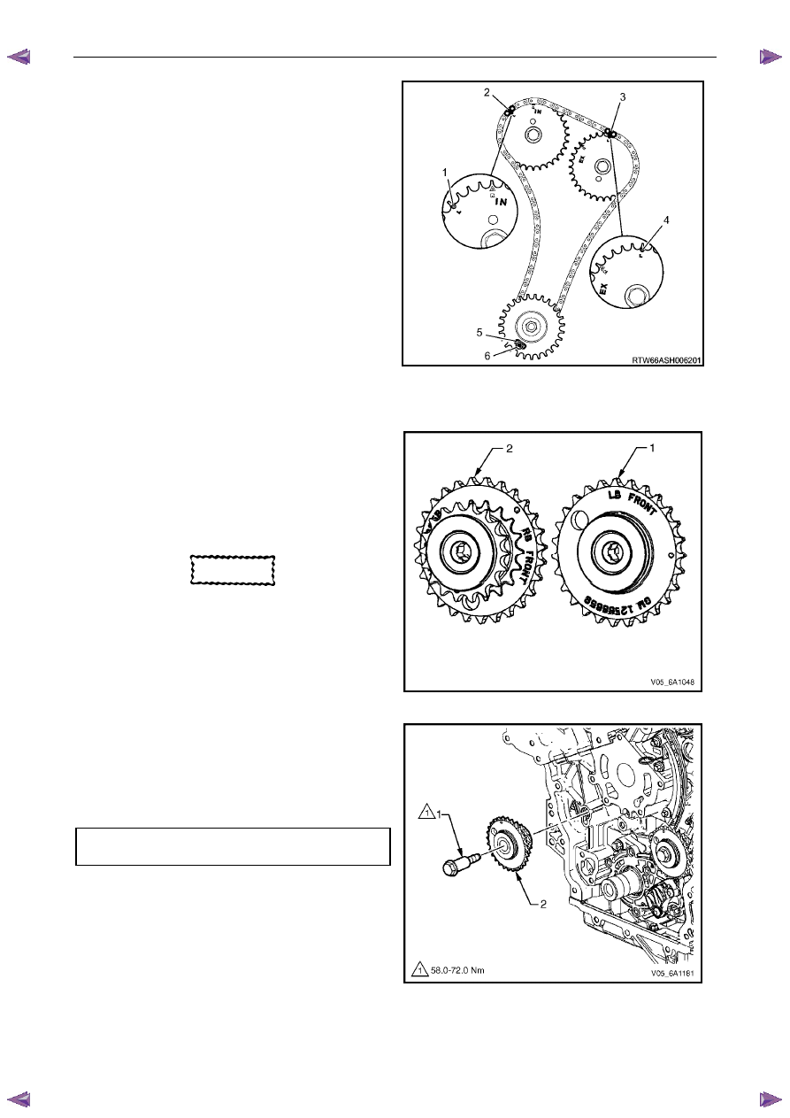
Verify the left-hand secondary timing chain timing
mark alignments (1 to 6).
Figure 6A1 – 167
Primary Timing chain Components
1
If previously removed, install the left-hand secondary
timing chain components, refer to Left-hand
Secondary Timing Chain Components in this Section.
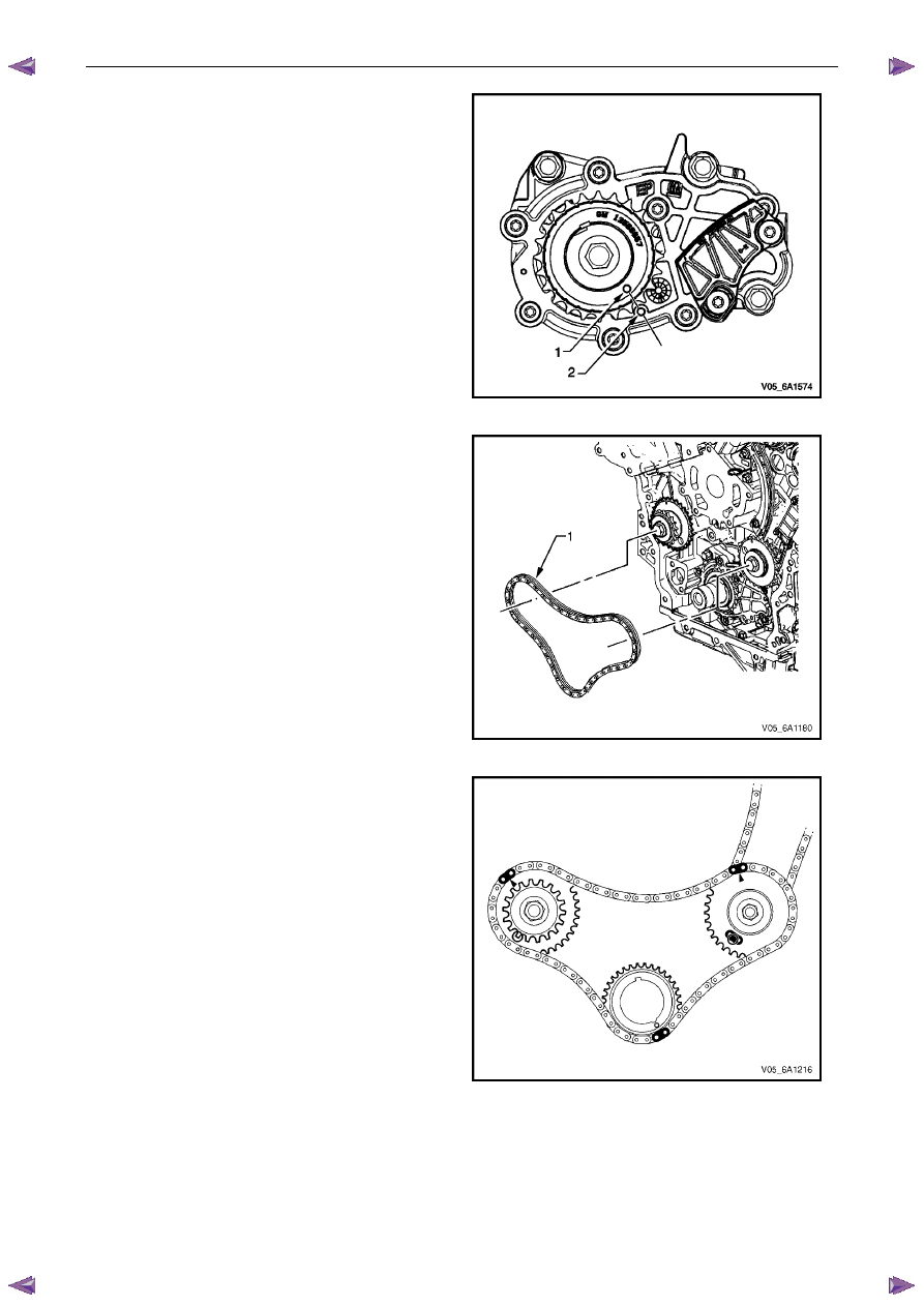
2
Ensure the right-hand camshaft intermediate
driveshaft sprocket (2) is selected and orientated
correctly.
CAUTION
The right-hand camshaft intermediate
driveshaft sprocket (2) is marked with the
letters RB and ‘FRONT’, and the left-hand
sprocket (1) is marked with the letters LB
and 'FRONT' Ensure the correct sprocket is
used and the FRONT text is facing forwards
when installed.
Figure 6A1 – 168
3
Install the right-hand camshaft intermediate driveshaft
sprocket (2).
4
Install the driveshaft sprocket bolt (1) and tighten to
the correct torque specification.
Camshaft intermediate driveshaft sprocket
attaching bolt torque specification. . ...58.0 – 72.0 Nm
Figure 6A1 – 169
Engine Mechanical – V6
Page 6A1–122
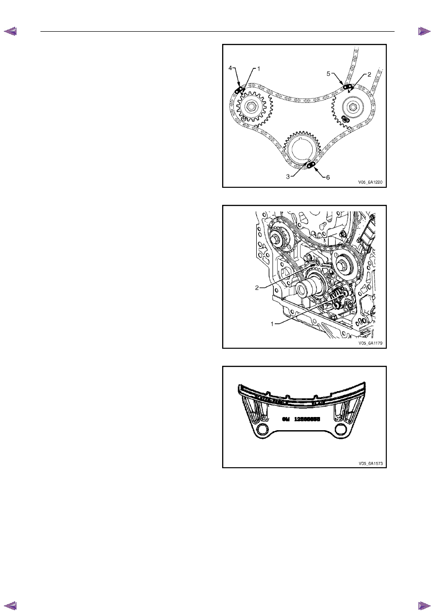
5
Ensure that the crankshaft sprocket timing mark (1) is
aligned with the indexing mark (2) on the oil pump
housing.
Figure 6A1 – 170
6
Install the primary timing chain (1).
Figure 6A1 – 171
7
Wrap the primary timing chain around the large
sprockets of each camshaft intermediate driveshaft
sprocket and the crankshaft sprocket aligning the
bright plated chain links as follows:
Figure 6A1 – 172

Engine Mechanical – V6
Page 6A1–123
8
The left-hand camshaft intermediate driveshaft
sprocket timing mark (1) will align with a bright plated
primary timing chain link (2).
Figure 6A1 – 173
9
The right-hand camshaft intermediate driveshaft
sprocket timing mark (1) will align with a bright plated
primary timing chain link (2).
Figure 6A1 – 174
10
The crankshaft sprocket timing mark (1) will align with
a bright plated timing chain link (2).
Figure 6A1 – 175
Engine Mechanical – V6
Page 6A1–124
11
Ensure all the timing marks (1, 2 and 3) are properly
aligned with the bright plated timing chain links (4, 5
and 6).
Figure 6A1 – 176
N O T E
Do not remove the primary timing chain lower
guide (1). The primary timing chain lower guide
is not serviced separately. If the primary timing
chain lower guide must be replaced, the oil
pump assembly (2) must be replaced.
Figure 6A1 – 177
12
Ensure the primary timing chain upper guide is
selected and orientated correctly.
Figure 6A1 – 178
Нет комментариевНе стесняйтесь поделиться с нами вашим ценным мнением.
Текст