Isuzu KB P190. Manual — part 1142
7B-4 MSG MODEL
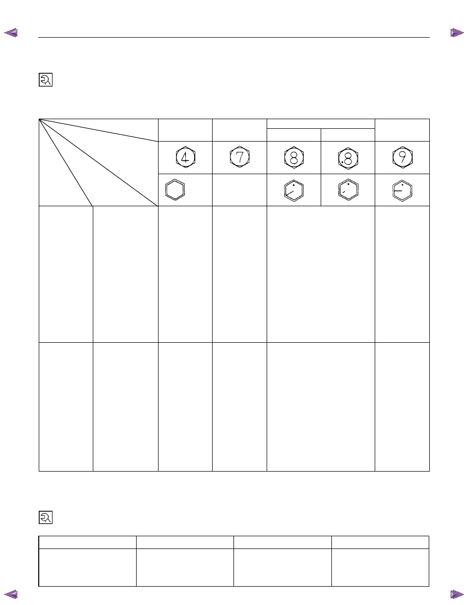
TORQUE SPECIFICATION
STANDDARD BOLTS
The torque values given in the following table should be applied where a particular torque is not specified.
N
⋅m (kgf⋅m/lb⋅ft)
Strength 4.8/4T
7T
8.8
9.8/9T
Class
Refined
Non-Refined
Bolt Identifi-
cation
Bolt
Diameter
××××
Pitch (mm)
No mark
-
M6
× 1.0
6 (0.6 / 52 lb.in)
7 (0.7 / 61 lb.in)
8 (0.8 / 69 lb.in)
-
M8
× 1.25
13 (1.3 / 113
lb.in)
17 (1.7 / 12)
20 (2.0 / 14)
24 (2.4 / 17)
M10
× 1.25
27 (2.8 / 20)
37 (3.8 / 27)
42 (4.3 / 31)
50 (5.1 / 37)
M12
× 1.25
61 (6.3 / 45)
76 (7.8 / 56)
87 (8.9 / 64)
95 (9.7 / 70)
M14
×1.5
96 (9.8 / 71)
116 (11.8 / 85)
133 (13.6 / 98)
142 (14.5 / 105)
M16
× 1.5
130 (13.3 / 96)
170 (17.3 / 125)
193 (19.7 / 143)
200 (20.4 / 148)
M18
× 1.5
188 (19.2 / 139)
244 (24.9 / 180)
278 (28.3 / 205)
287 (29.3 / 212)
M20
× 1.5
258 (26.3 / 190)
337 (34.4 / 249)
385 (39.3 / 284)
396 (40.4 / 292)
M22
× 1.5
332 (33.9 / 245)
453 (46.3 / 335)
517 (52.7 / 381)
530 (54.1 / 391)
M24
× 2.0
449 (45.8 / 331)
570 (58.2 / 421)
651 (66.3 / 480)
692 (70.6 / 511)
*
M10
× 1.5
26 (2.7 / 20)
36 (3.7 / 27)
41 (4.2 / 30)
48 (4.9 / 35)
*
M12
× 1.75
57 (5.8 / 42)
71 (7.2 / 52)
80 (8.2 / 59)
89 (9.1 / 66)
*
M14
× 2.0
89 (9.1 / 66)
110 (11.2 / 81)
125 (12.7 / 92)
133 (13.6 / 98)
*
M16
× 2.0
124 (12.7 / 92)
162 (16.5 / 119)
185 (18.9 / 137)
191 (19.5 / 141)
Flange Bolt
M6
× 1.0
7 (0.7 / 61 lb.in)
8 (0.8 / 69 lb.in)
9 (0.9 / 78 lb.in)
-
M8
× 1.25
15 (1.5 / 11)
19 (1.9 / 14)
22 (2.2 / 16)
26 (2.7 / 20)
M10
× 1.25
31 (3.2 / 23)
41 (4.2 / 30)
47 (4.8 / 35)
56 (5.7 / 41)
M12
× 1.25
69 (7.0 / 51)
85 (8.7 / 63)
97 (9.9 / 72)
106 (10.8 / 78)
M14
× 1.5
104 (10.6 / 77)
126 (12.8 / 93)
144 (14.6 / 106)
154 (15.7 / 114)
M16
× 1.5
145 (14.8 / 127)
188 (19.2 / 139)
214 (21.8 / 158)
221 (22.5 / 163)
M18
× 1.5
-
-
-
-
M20
× 1.5
-
-
-
-
M22
× 1.5
-
-
-
-
M24
× 2.0
-
-
-
-
*
M10
× 1.5
30 (3.1 / 22)
40 (4.1 / 30)
46 (4.7 / 34)
54 (5.5 / 40)
*
M12
× 1.75
64 (6.5 / 47)
78 (8.0 / 58)
89 (9.1 / 66)
99 (10.1 / 73)
*
M14
× 2.0
97 (9.9 / 72)
119 (12.1 / 88)
135 (13.8 / 99.7)
144 (14.7 / 107)
*
M16
× 2.0
137 (14.0 / 101)
178 (18.2 / 132)
203 (20.7 / 132)
210 (21.5 / 155)
The asterisk * indicates that the bolts are used for female-threaded parts that are made of soft materials such as
casting, etc.
FLARE NUTS
Pipe diameter mm (in)
Torque N
⋅⋅⋅⋅m (kgf⋅⋅⋅⋅m/lb⋅⋅⋅⋅ft)
Pipe diameter mm (in)
Torque N
⋅⋅⋅⋅m (kgf⋅⋅⋅⋅m/lb⋅⋅⋅⋅ft)
4.76 (0.187)
16 (1.6 / 12)
10.00 (0.394)
54 (5.5 / 40)
6.35 (0.250)
26 (2.7 / 20)
12.00 (0.472)
88 (9.0 / 65)
8.00 (0.315)
44 (4.5 / 33)
15.00 (0.591)
106 (10.8 / 78)
Standard Hex.
Head Bolt
MSG MODEL 7B-5
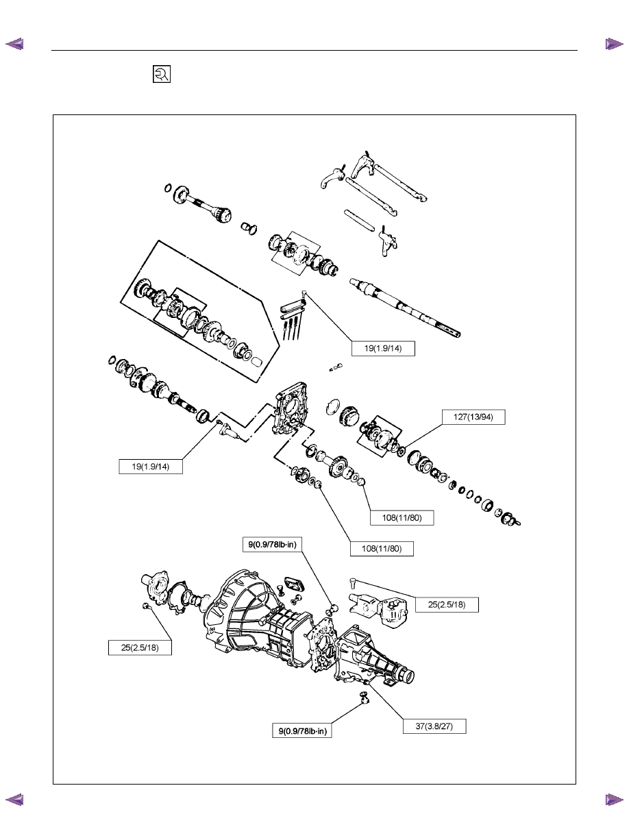
SPECIAL PARTS FIXING NUTS AND BOLTS
N
⋅⋅⋅⋅m (kgf⋅⋅⋅⋅m/lb⋅⋅⋅⋅ft)
RTW77BXF000101
7B-6 MSG MODEL
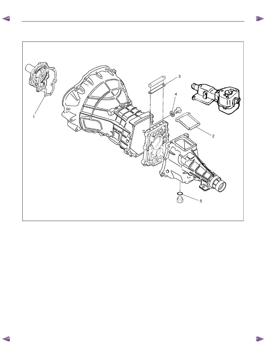
REPAIR KIT
RTW47BLF000201
1. Case to front cover gasket
2. Control box gasket
3. Plate gasket
4. Filler plug O-ring
5. Drain plug O-ring
MSG MODEL 7B-7
REMOVAL AND INSTALLATION
Read this Section carefully before performing any removal and installation procedure. This Section gives you
important points as well as the order of operation. Be sure that you understand everything in this Section before you
begin.
Important Operations - Removal
Battery Cable
Disconnect the negative (-) cable from the battery terminal.
Engine Hood
Apply setting marks to the engine hood and the engine hood
hinges before removing the engine hood.
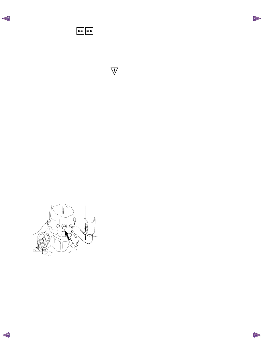
Gear Shift Lever
1. Place the gear shift lever in the neutral position.
2. Remove the gear shift lever knob.
3. Remove the front console assembly.
4. Remove the gear shift lever grommet and dust cover.
5. Remove the gear shift lever cover bolts.
6. Remove the gear shift lever.
Note:
Cover the shift lever hole to prevent the entry of foreign
material into the transmission.
Lifting the Vehicle
1. Jack up the vehicle.
2. Place chassis stands at the front and the rear of the vehicle.
Transmission Oil Draining
1. Remove the transmission oil drain plug.
2. Replace the drain plug after draining the oil.
Нет комментариевНе стесняйтесь поделиться с нами вашим ценным мнением.
Текст