Isuzu KB P190. Manual — part 238
6B – 8 ENGINE COOLING
Draining and Refilling Cooling System
Before draining the cooling system, inspect the system and
perform any necessary service to ensure that it is clean, does
not leak and is in proper working order. The engine coolant
(EC) level should be between the “MIN" and “MAX" lines of
reserve tank when the engine is cold. If low, check for leakage
and add EC up to the “MAX" line.
There should not be any excessive deposit of rust or scales
around the radiator cap or radiator filler hole, and the EC
should also be free from oil.
Replace the EC if excessively dirty.
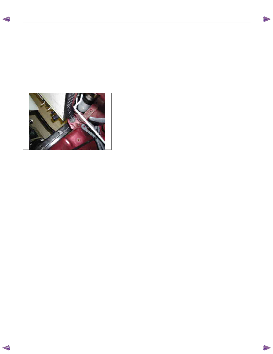
P1010064
1. Completely drain the cooling system by opening the drain
plug at the bottom of the radiator.
2. Remove the radiator cap.
WARNING: To avoid the danger of being burned, do not
remove the cap while the engine and radiator are still hot.
Scalding fluid and steam can be blown out under
pressure.
3. Disconnect all hoses from the EC reserve tank.
Scrub and clean the inside of the reserve tank with soap
and water. Flush it well with clean water, then drain it.
Install the reserve tank and hoses.
4. Refill the cooling system with the EC using a solution that is
at least 50 percent antifreeze.
Procedure for filling with coolant (in case of full change)
• Make sure that the engine is cool.
• Open radiator cap pour coolant up to filler neck.
• Pour coolant into reservoir tank up to “MAX" line.
• Tighten radiator cap and start the engine. After idling for 2
to 3 minutes, stop the engine and reopen radiator cap. If the
water level is lower, replenish.
WARNING: When the coolant is heated to a high
temperature, be sure not to loosen or remove the radiator
cap. Otherwise you might get scalded by not vapor or
boiling water. To open the radiator cap, put a piece of
thick cloth on the cap and loosen the cap slowly to reduce
the pressure when the coolant has become cooler.
ENGINE COOLING 6B – 9
• After tightening radiator cap, warm up the engine at about
2000 rpm. Set heater adjustment to the highest temperature
position, and let the coolant circulate also into heater water
system.
• Check to see the thermostat has opened through the
needle position of water thermometer, conduct a 5–minute
idling again and stop the engine.
• When the engine has been cooled, check filler neck for
water level and replenish if required. Should extreme
shortage of coolant is found, check the cooling system and
reservoir tank hose for leakage.
• Pour coolant into the reservoir tank up to “MAX" line.
6B – 10 ENGINE COOLING
WATER PUMP
REMOVAL AND INSTALLATION
Read this Section carefully before performing any removal and installation procedure. This Section gives you
important points as well as the order of operation. Be sure that you understand everything in this Section before you
begin.
Removal
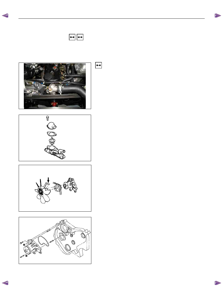
1. Radiator Upper Hose
1) Partially drain the engine coolant.
2) Remove the radiator upper hose.
031R300003
2. Water Outlet Pipe
1) Disconnect the turbocharger-cooling pipe from outlet
pipe.
2) Loosen the fixing bolt and remove the water outlet
bolt.
3. Thermostat
Remove the thermostat from the thermostat housing.
Take care not to damage the thermostat.
4. Upper Fan Shroud
5. Fan and Fan Clutch
1) Loosen the fan clutch nuts.
2) Remove the fan together with the fan clutch. Take
care not to damage the radiator core.
6. Fan Drive Belt and Pulley
1) Loosen the tension adjust bolt on the generator.
2) Remove the fan drive belt with the fan pulley.
030R300001
7. Water
Pump
1) Remove the water pump bolts.
2) Remove the water pump.
030R300002
ENGINE COOLING 6B – 11
Inspection and Repair
The water pump is not disassembled type.
Make necessary parts replacement if extreme wear or
damage is found during inspection. Should any of the
following problems occur, the entire water pump assembly
must be replaced.
・ Cracks in the water pump body
・ Coolant leakage from the seal unit
・ Excessive radial play or abnormal noise in the fan center
when rotate by hand
・ Excessive thrust play in the fan center (Standard play: less
than 0.2mm)
・ Cracks or corrosion in the impeller
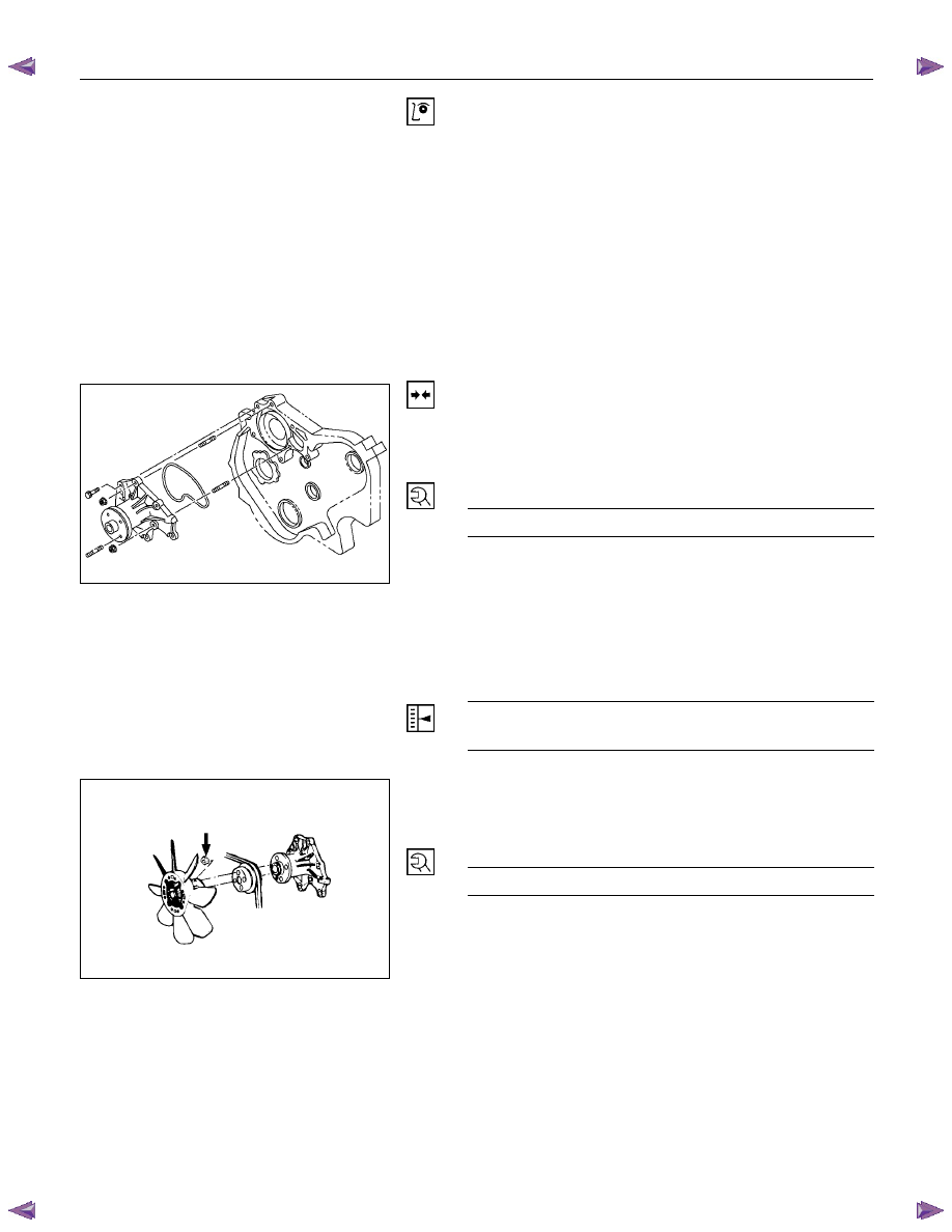
Installation
1. Water
Pump
1) Install the water pump with new gasket.
2) Tighten bolts and nuts to specified torque.
Water Pump Bolt/Nut Torque
N·m(kg·m/lb ft)
20 (2.0/14)
2. Fan Drive Belt and Pulley
1) Install the fan drive belt and fan pulley.
2) Apply tension to the fan drive belt by moving the
generator.
3) Apply a force of 98N(10kg/22 lb) to the drive belt mid-
portion to check the drive belt deflection.
Fan Drive Belt Deflection
mm (in)
New belt: 4-7(0.16-0.28)
Reuse belt: 6-9(0.24-0.35)
030R300002
030R300001
3. Fan and Fan Clutch
1) Install the fan and fan clutch to pulley.
2) Tighten the nuts to specified torque.
Fan Clutch Nut Torque
N·m(kg·m/lb in)
8(0.8/69)
4. Upper Fan Shroud
Нет комментариевНе стесняйтесь поделиться с нами вашим ценным мнением.
Текст