Isuzu KB P190. Manual — part 1027
ON-VEHICLE SERVICE (AW30–40LE) 7A3-23
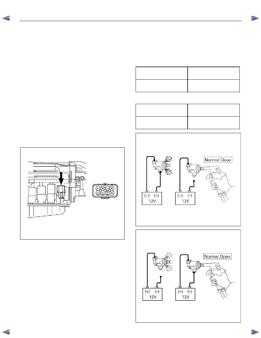
Solenoid
Inspection
1. Resistance check
• Using an ohmmeter, check the resistance
between each terminal (S1/S2/SL) and body.
Solenoid S1, S2 and lock-up solenoid SL
resistance:
11 – 15
Ω
Ω
Ω
Ω
(at 20
°°°°
C or 68
°°°°F)
(Reference) 12 – 16
Ω
Ω
Ω
Ω
(at 40
°°°°
C or 104
°°°°F)
• Using an ohmmeter, check the resistance
between each terminal (STH) and (STHG).
Pressure control solenoid resistance:
5 – 5.6
Ω
Ω
Ω
Ω
(at 20
°°°°
C or 68
°°°°F)
(Reference) 5.4– 6.1
Ω
Ω
Ω
Ω
(at 40
°°°°
C or 104
°°°°F)
220L100001
NOTE: If the pressure control solenoid resistance is not
within specification, replace the valve body assembly.
2. Operation check
Check the solenoid operation by blowing into an oil
hole as shown in the figure.
Solenoid S1 and S2 (Normal close type)
When battery terminal is
disconnected
No air leaks
When battery terminal is
connected
Air passes through
Lock-up solenoid SL (Normal open type)
When battery terminal is
disconnected
Air passes through
When battery terminal is
connected
No air leaks
244RX00001
244RY00005
7A3-24 ON-VEHICLE SERVICE (AW30–40LE)
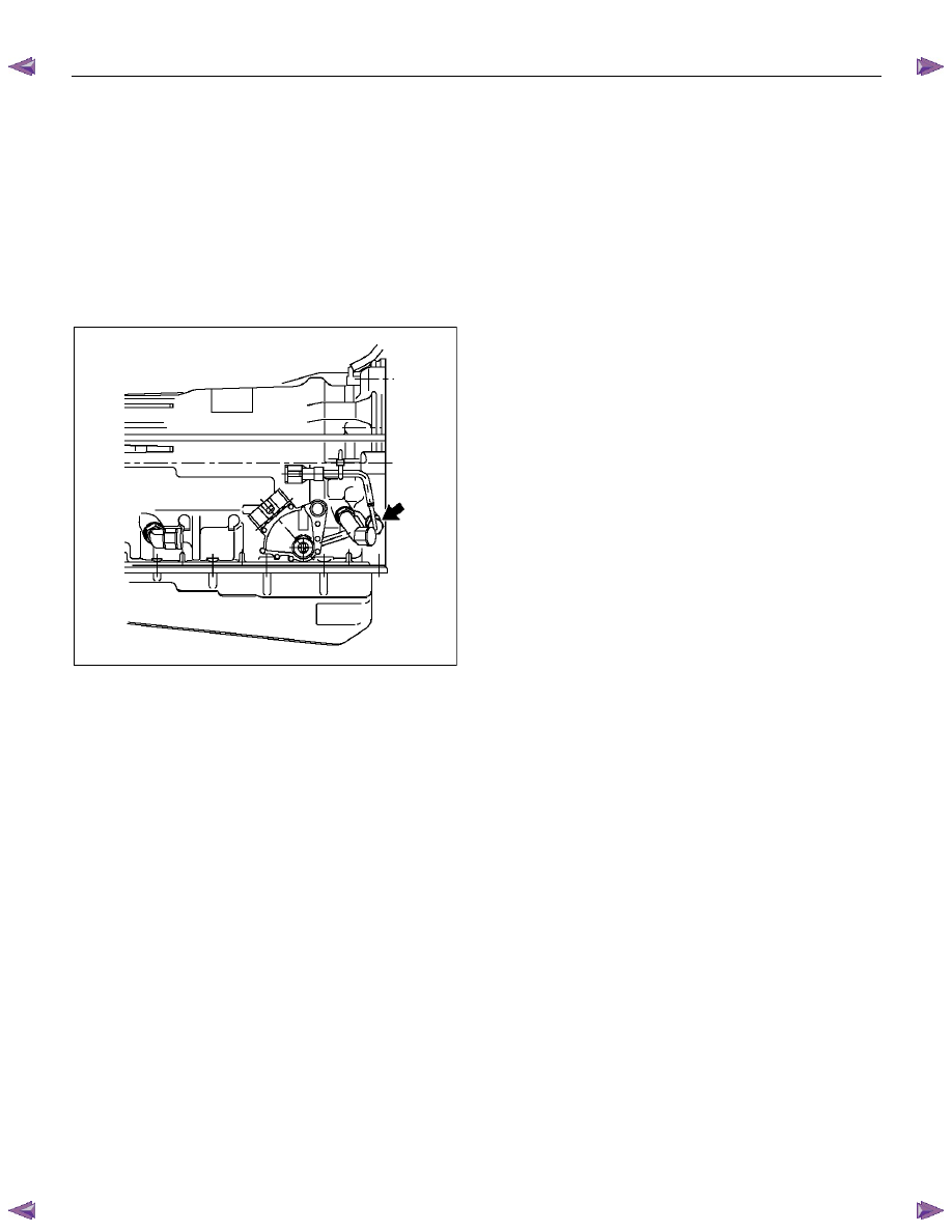
ATF Temperature Sensor
Inspection
1. Disconnect the front side ATF cooler pipe from the
elbow and remove the elbow.
2. Remove the ATF temperature sensor from the
transmission case.
3. Place the ATF temperature sensor in a container of
ATF.
RTW77ASH003501
4. Measure the resistance between each terminal,
while warming ATF.
Resistance: 0.5 – 30 k
Ω
Ω
Ω
Ω
(at 0
°°°°C – 120°°°°C or 32°°°°F –
248
°°°°F)
5.
If either of the measured values exceeds the
specified value, replace the ATF temperature
sensor.
Torque: 15 N
⋅⋅⋅⋅m (1.5 kgf⋅⋅⋅⋅m/11 Ib⋅⋅⋅⋅ft)
ON-VEHICLE SERVICE (AW30–40LE) 7A3-25
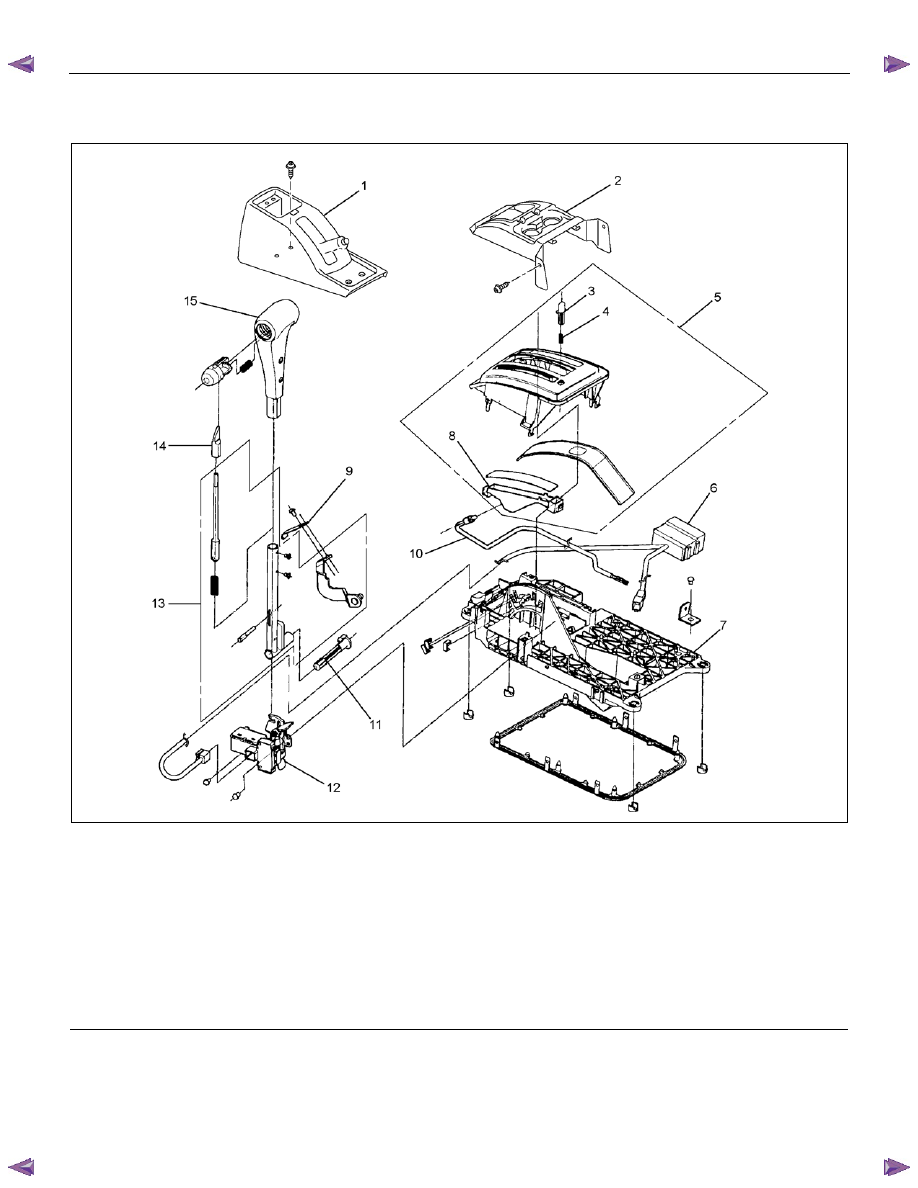
Select Lever
RTW77ALF000201
Legend
1. Rear
console
2. Front
console
3. Shift lock release button
4. Shift lock button spring
5. Upper housing
6. Interlock controller
7. Base
plate
8. Position indicator housing
9. Spring
plate
10. Lamp assembly
11. Grooved pin
12. Shift lock unit
13. Lever assembly
14. Sleeve
15. Select lever knob
7A3-26 ON-VEHICLE SERVICE (AW30–40LE)
Remove or Disconnect
1. Block the wheels.
2. Disconnect the negative battery cable.
3. Remove the rear console and the front console.
4. Remove the 2 screws fixing the select lever knob.
5. Remove the knob together with the knob button and
spring from the lever.
6. Turn the sleeve counterclockwise to remove it.
Make a note of the number of turns required to free
the sleeve.
7. Remove the harness connectors from the base
plate.
8. Remove the upper housing (held in place by 4
latched fasteners).
9. Remove the lamp assembly by turning it
counterclockwise.
10. Remove the spring plate.
11. Remove the grooved pin.
12. Disconnect the shift cable from the select lever.
13. Remove the lever assembly by pressing the rod
down (lever in N position).
14. Remove the harness connectors from the shift lock
unit, then remove the shift lock unit.
15. Remove the interlock controller.
16. If the replacement of shift lock release button or
shift lock button spring is required, remove the
position indicator housing, the shift lock button
spring and shift lock release button can be
removed.
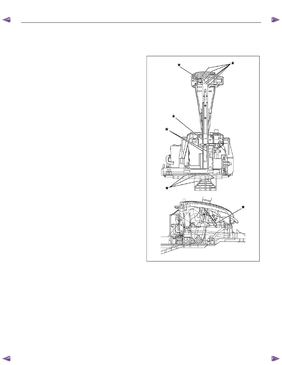
Install or Connect
NOTE
Apply MULTEMP No. 2 grease (or equivalent) to the
select lever. Refer to the illustration.
RTW77ALH000201
1. Install the interlock controller.
2. Install the shift lock unit and connect the harness to
the shift lock unit.
3. Install the lever assembly to the base plate.
a. Insert and secure the shaft and connect the
cable.
b. Insert pawled end of the shaft into the base plate
hole.
c. Insert the detent pin of the shaft into detent
aperture (lever assembly in N position).
d. Install the grooved pin.
Нет комментариевНе стесняйтесь поделиться с нами вашим ценным мнением.
Текст