Isuzu KB P190. Manual — part 1010
7A2-74 TRANSMISSION CONTROL SYSTEM (AW30–40LE)
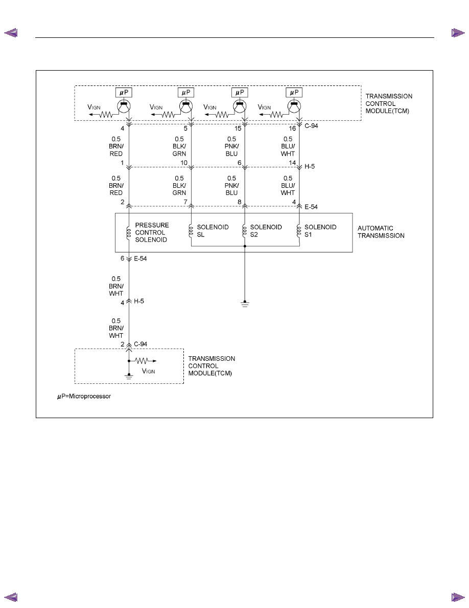
DTC P0751 (Flash Code 41)
RTW77ALF001501
Circuit Description
The shift solenoid S1 changes the hydraulic route with
the signals from the TCM according to the vehicle
speed and the throttle opening to control shifting. When
the solenoid S1 or S2 fails, the hydraulic circuit is
mechanically operated as a backup.
Condition For Running The DTC
All of the following conditions are met.
(1) All of the following conditions are met for 2
seconds or more continuously.
• The supply voltage is more than 10.2 volts and
less than 15.5 volts.
• DTC U2104 is not detecting failure or not
deciding failure.
• DTC U2105 is not detecting failure or not
deciding failure.
• Engine revolution signal is not detecting failure
or not deciding failure.
• The engine revolution is more than 550rpm.
(2) Oil temperature is more than 20
°C (68°F), and
water temperature signal is more than 70
°C
(158
°F).
(3) 20 seconds or more passed after D position is
detected.
(4) Oil temperature sensor is not deciding failure.
TRANSMISSION CONTROL SYSTEM (AW30–40LE) 7A2-75
(5) Engine coolant temperature sensor is not detecting
failure or not deciding failure.
(6) Engine revolution rpm is more than 600 rpm.
(7) Engine revolution sensor is not detecting failure or
not deciding failure.
(8) T/F condition is high.
(9) T/F Hi-Low SW is not detecting failure or not
deciding failure.
(10) Output revolution sensor is not detecting failure or
not deciding failure.
(11) S1 solenoid is not detecting failure or not deciding
failure. (Electric failure)
(12) S2 solenoid is not detecting failure or not deciding
failure. (Electric failure)
(13) Selector position switch is not detecting failure or
not deciding failure.
(14) DTC U2104 is not detecting failure or not deciding
failure.
(15) DTC U2105 is not detecting failure or not deciding
failure.
(16) Input revolution sensor is not deciding.
(17)
Throttle signal is not detecting failure or not
deciding failure.
(18) Not emergency mode.
(19) Engine torque signal is not detecting failure or not
deciding failure.
(20) Pressure control solenoid is not detecting failure or
not deciding failure.
(21) All of the following conditions are met.
• Device Control is not operating.
• Disable Normal Communication Service is
receiving enable.
• DTC Clear is not operating.
Condition For Setting The DTC
The following conditions are detected two times or more
between ignition “ON” and ignition “OFF”.
2 second passed after gear change output.
• The TCM detects equivalent of 4th gear ratio for 1
second in case of 1st gear output.
- The throttle position is more than 8% and less than
100%.
- The vehicle speed is more than 7 km/h (4 mph).
• The TCM detects equivalent of 3rd gear ratio for 1
second in case of 2nd gear output.
- The throttle position is more than 8% and less than
100%.
- The vehicle speed is more than 5 km/h (3 mph)
and less than 30 km/h (19 mph).
Action Taken When The DTC Sets
• No input revolution sensor failure detection.
• MIL request “ON”. (EURO 4 only)
• Check Trans “ON”.
• DTC
stored.
Conditions For Clearing The DTC
• The DTC can be cleared from the TCM history by
using a scan tool.
• The DTC will be cleared from history when the
vehicle has achieved 40 warm-up cycles without a
failure reported.
• After more than 1 second has elapsed after the
ignition key has been turned “ON”, short between
No.11 and No.4 (ground) of DLC (Data Link
Connector). Then, after 1 second, but within 6
seconds, discontinue shorting.
Diagnostic Aids
• Inspect the wiring for poor electrical connection at the
TCM. Look for possible bent, backed out, deformed
or damaged terminals. Check for weak terminal
tension as well. Also check for a chafed wire that
could short to bare metal or other wiring.
Inspect for a broken wire inside the insulation.
• When diagnosing for a possible intermittent short or
open condition, move the wiring harness while
observing test equipment for a change.

7A2-76 TRANSMISSION CONTROL SYSTEM (AW30–40LE)
Circuit/System Testing DTC P0751
Step Action Value(s)
YES
NO
1
Was the On-Board Diagnostic (OBD) System Check
performed?
— Go
to
Step 2 Go
to
OBD
System Check
2
1. Install a scan tool.
2. Turn “ON” the ignition.
3. Review and record scan tool data.
4. Operate the vehicle within scan tool data.
Does a scan tool indicate DTC P0751?
— Go
to
Step 3 Refer
to
Diagnostic Aids
3
Perform the transmission fluid checking procedure.
Refer to checking Transmission Fluid level and
Condition in Automatic Transmission 7A section.
If the problem found, repair or replaces necessary.
Was the problem found?
— Go
to
Step 8 Go
to
Step 4
4
Observe the commanded gear and current gear on a
scan tool.
1. Turn “ON” the ignition with engine “ON”.
2. Road testing the vehicle.
3. The throttle position is more than 8%.
4. The vehicle speed is more than 5 km/h (3 mph).
Did the TCM detect 4th gear ratio in case of 1st gear
target, and 3rd gear ratio in case of 2nd gear target?
Above conditions were indicated on a scan tool
display?
— Refer
to
Diagnostic Aids
Go to Step 5
5
Check the following items.
• Check the shift solenoid valve S1. (Refer to
Section 7A3)
• Shift solenoid valve S1 stuck “OFF” the release
position (Refer to Section 7A4)
• Misaligned or damaged valve body gasket.
• Restricted apply passage.
If the problem found, replaces necessary.
Was the problem found?
— Go
to
Step 8 Go
to
Step 6
6
Check the DTC on a scan tool.
Is DTC found on a scan tool?
— Go
to
Step 7 Go
to
Step 8
7
Replace the valve body. (Refer to Section 7A4).
Is the action complete?
— Go
to
Step 8 —

TRANSMISSION CONTROL SYSTEM (AW30–40LE) 7A2-77
Step Action Value(s)
YES
NO
8
1. Reconnect all previously disconnected harness
connector(s).
2. Clear the DTCs with a scan tool.
3. Turn “OFF” the ignition.
4. Start the engine.
5. Operate the vehicle within the Conditions For
Running the DTC. You may also operate the
vehicle within the conditions that you observed
from the Freeze Frame/ Failure Records.
Did the DTC fail this ignition?
—
Go to Step 2 Go
to
Step 9
9
Observe the stored information, Capture info with a
scan tool.
Are there any DTCs that you have not diagnosed?
—
Go to
Diagnostic
Trouble Code
(DTC) List
Verify repair
Нет комментариевНе стесняйтесь поделиться с нами вашим ценным мнением.
Текст