Isuzu KB P190. Manual — part 822
Engine Management – V6 – Diagnostics
Page 6C1-2–10
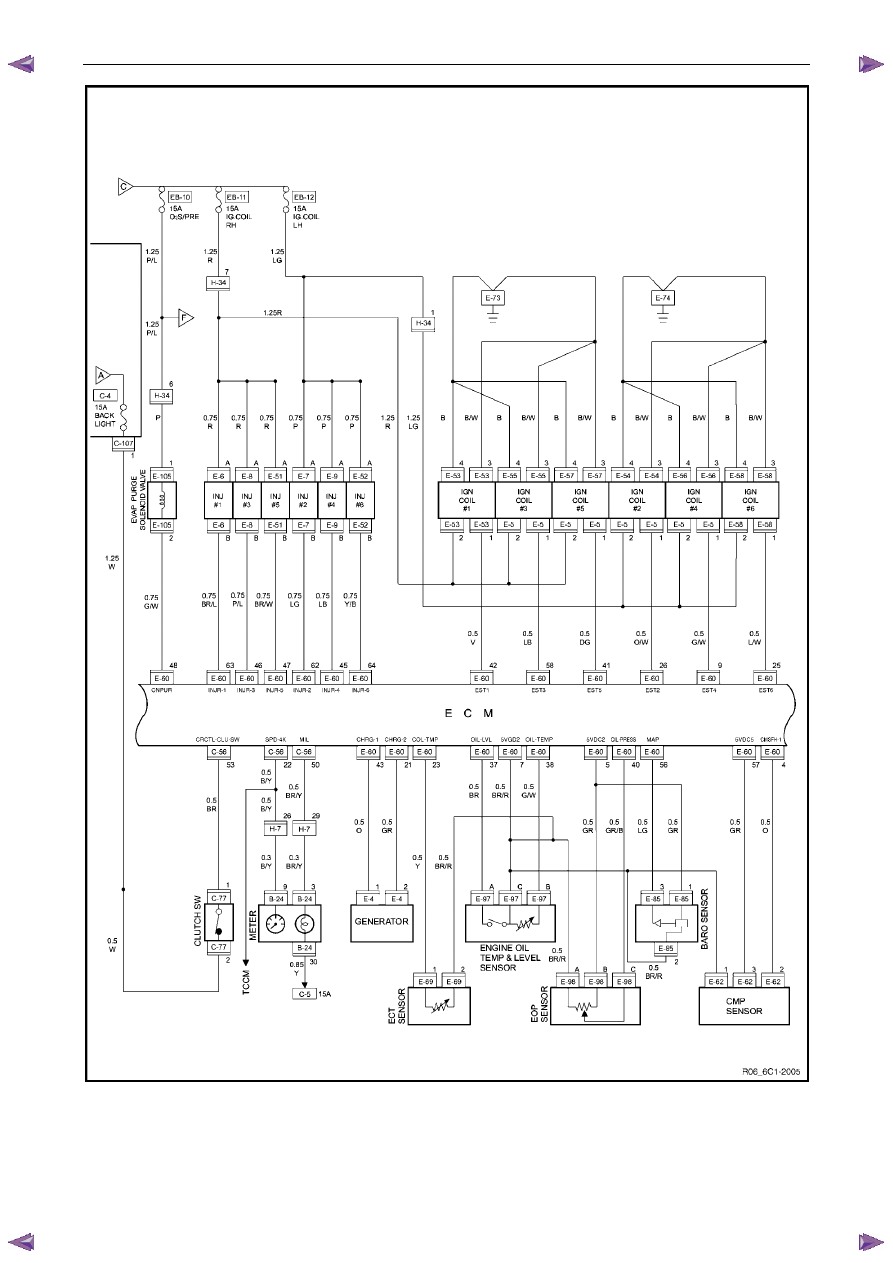
Figure 6C1-2 – 3

Engine Management – V6 – Diagnostics
Page 6C1-2–11
Figure 6C1-2 – 4
Engine Management – V6 – Diagnostics
Page 6C1-2–12
3.2
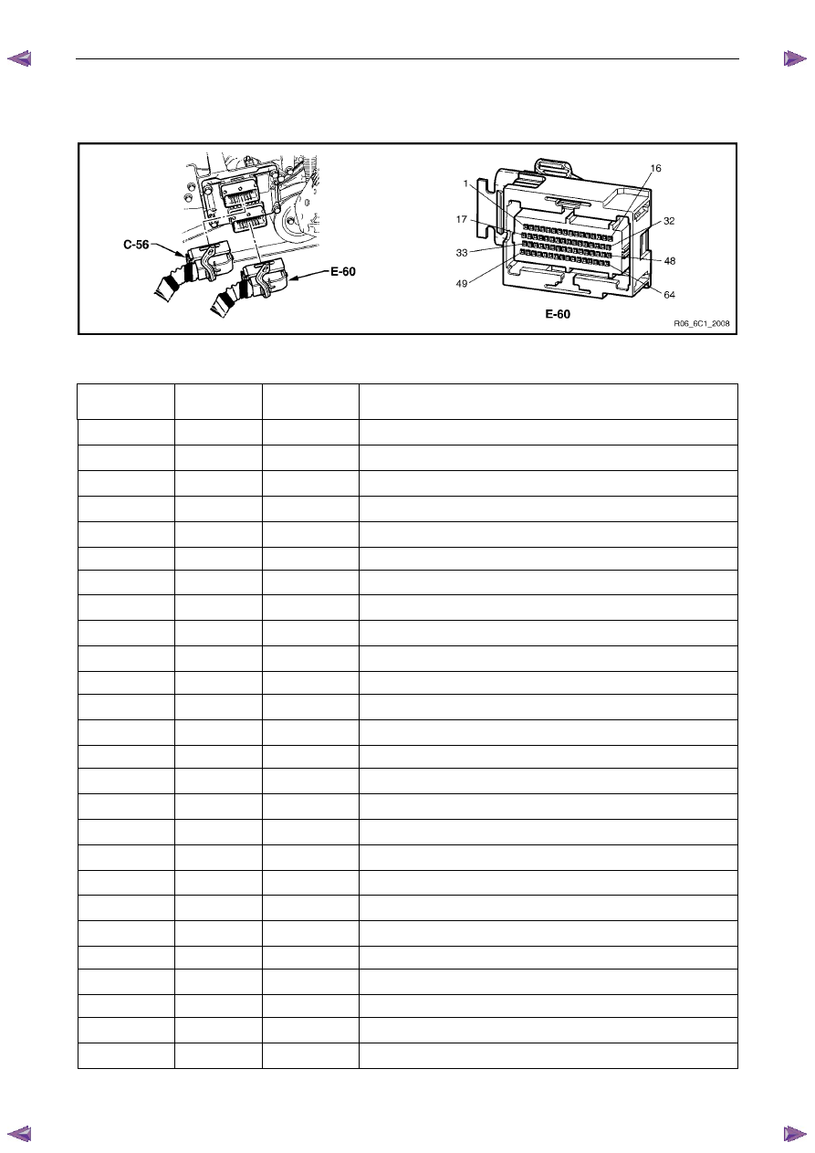
ECM Connector End Views
Engine Control Module Connector E-60
Figure 6C1-2 – 5
Terminal / Pin
Wire Colour
Circuit
Description
Function
E-60–1 BR
KNK_RET2
Low Reference – Knock Sensor Bank 2
E-60–2 LG
IN_PMP_2
B2S1 HO2S Input Pump Current (Bank 2 Sensor 1)
E-60–3 O
IN_PMP_1
B1S1 HO2S Input Pump Current (Bank 1 Sensor 1)
E-60–4 O
CMSFH_1
CMP Sensor Signal – Intake Bank 1
E-60–5 GR 5VDC2
5 Volt Reference – 6
E-60–6
Not Used
E-60–7 BR/R 5VGD2
Low Reference – Ground 2
E-60–8 V TPS_2
TP Sensor 2 Signal
E-60–9 G/W EST4
EST 4 Control
E-60–10 W
ENG_SPD
CKP Sensor High
E-60–11
Not Used
E-60–12
Not Used
E-60–13
Not Used
E-60–14
Not Used
E-60–15 BR ETC_POS
TAC Motor Control (Positive)
E-60–16 V/W
O2_HTR_1
B1S1 HO2S Heater Low Reference (Bank 1 Sensor 1)
E-60–17 GR
KNK_RET1
Low Reference – Knock Sensor Bank 1
E-60–18 BR/W
O2_RTN_2
B2S1 HO2S Low Signal (Bank 2 Sensor 1)
E-60–19 V HI_SIG_1
B1S1 HO2S High Signal (Bank 1 Sensor 1)
E-60–20
Not Used
E-60–21 GR CHRG_2
Generator Field Duty Cycle Signal (‘F’ Terminal)
E-60–22
Not Used
E-60–23 Y COL_TMP
ECT Sensor Signal
E-60–24
Not Used
E-60–25 L/W EST6
EST 6 Control
E-60–26 O/W EST2
EST 2 Control
Engine Management – V6 – Diagnostics
Page 6C1-2–13
E-60–27
Not Used
E-60–28
Not Used
E-60–29
Not
Used
E-60–30
Not
Used
E-60–31 Y ETC_NEG
TAC Motor Control (Negative)
E-60–32 L
O2_HTR_2
B2S1 HO2S Heater Low Control (Bank 2 Sensor 1)
E-60–33 L KNK1
Knock Sensor 1 Signal (Bank 1)
E-60–34 V/W HI_SIG_2
B2S1 HO2S High Signal (Bank 2 Sensor 1)
E-60–35 V/W PMP_1
B1S1 HO2S Pump Current (Bank 1 Sensor 1)
E-60–36
Not Used
E-60–37 BR OIL_LVL
Oil Level Switch Signal
E-60–38 G/W OIL_TMP
Oil Temperature Sensor Signal
E-60–39 BR/T 5VGD3
Low Reference – Ground 3
E-60–40 GR/B
OIL_PRESS
Oil Pressure Sensor Signal
E-60–41 DG EST5
EST 5 Control
E-60–42 V EST1
EST 1 Control
E-60–43 O CHRG_1
Generator Turn On Signal (‘L’ Terminal)
E-60–44
Not Used
E-60–45 LB INJR_4
Fuel Injector 4 Control
E-60–46 P/L INJR_3
Fuel Injector 3 Control
E-60–47 BR/W INJR_5
Fuel Injector 5 Control
E-60–48 G/W
CNPUR
EVAP Canister Purge Solenoid Control
E-60–49
GR/B
RET5
CKP Sensor Shield Return
E-60–50 LB KNK2
Knock Sensor 2 Signal (Bank 2)
E-60–51 W PMP_2
B2S1 HO2S Pump Current (Bank 2 Sensor 1)
E-60–52 BR/G
O2_RTN_1
B1S1 HO2S Low Signal (Bank 1 Sensor 1)
E-60–53
Not Used
E-60–54 GR 5VDC2
5 Volt Reference – 2
E-60–55 G TPS-1
TP Sensor 1 Signal
E-60–56 LG MAP
MAP Sensor Signal
E-60–57 GR 5VDC5
5 Volt Reference – 5
E-60–58 LB EST3
EST 3 Control
E-60–59 B 5VGD6
CKP Sensor Low – Ground 6
E-60–60
Not Used
E-60–61
Not Used
E-60–62 LG INJR_2
Fuel Injector 2 Control
E-60–63 BR/L INJR_1
Fuel Injector 1 Control
E-60–64 Y/B INJR_6
Fuel Injector 6 Control
Нет комментариевНе стесняйтесь поделиться с нами вашим ценным мнением.
Текст