Isuzu KB P190. Manual — part 1041
UNIT REPAIR (AW30–40LE)
7A4–29
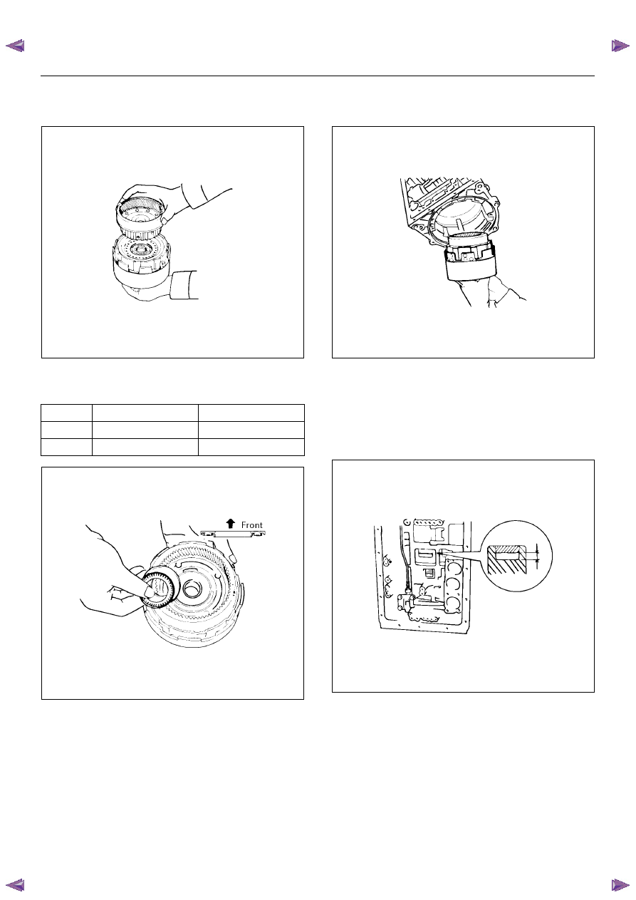
17. Align the spline of the front planetary gear with the
flukes of the discs and install the front planetary
gear to the forward clutch.
247RY00017
18. Coat the bearing and race with petroleum jelly and
install them onto the ring gear.
Bearing and race diameter (Reference)
247RY00019
19. Install the assembled direct clutch, forward clutch
and front planetary ring gear into the transmission
case.
247RY00018
• Using vernier calipers, measure the distance
between the sun gear input drum and direct
clutch drum as shown in the figure.
Height: 2.5– 4.5 mm (0.098 – 0.177 in)
If the values are nonstandard, check for an
improper installation.
248RY00024
Inside
Outside
Bearing
35.15 mm (1.384 in)
53.65 mm (2.112 in)
Race
35.15 mm (1.384 in)
53.65 mm (2.112 in)
7A4–30
UNIT REPAIR (AW30–40LE)
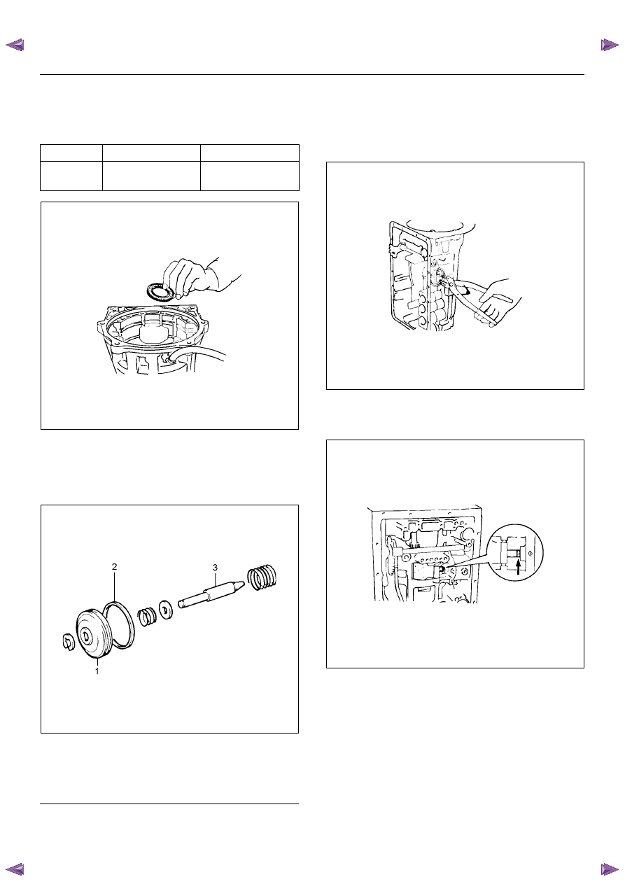
Coat the assembled bearing and race with
petroleum jelly and install it onto the forward
clutch.
Assembled bearing and race diameter
(Reference)
248RY00025
20. Assembly second coast brake piston assembly.
Coat the oil seal ring with ATF and install it to the
second coast brake piston.
Install the washer, spring and piston to the piston
rod. Install the E-ring.
RUW37ASH004401
EndOFCallout
21. Coat two new oil seals with ATF and install them to
the piston cover.
Install the spring, second coast brake piston
assembly and piston cover to the transmission
case.
Using snap ring pliers, install the snap ring.
248RY00027
22. Check piston stroke of second coast brake
Place a mark on the second coast brake piston rod
as shown in the figure.
248RY00005
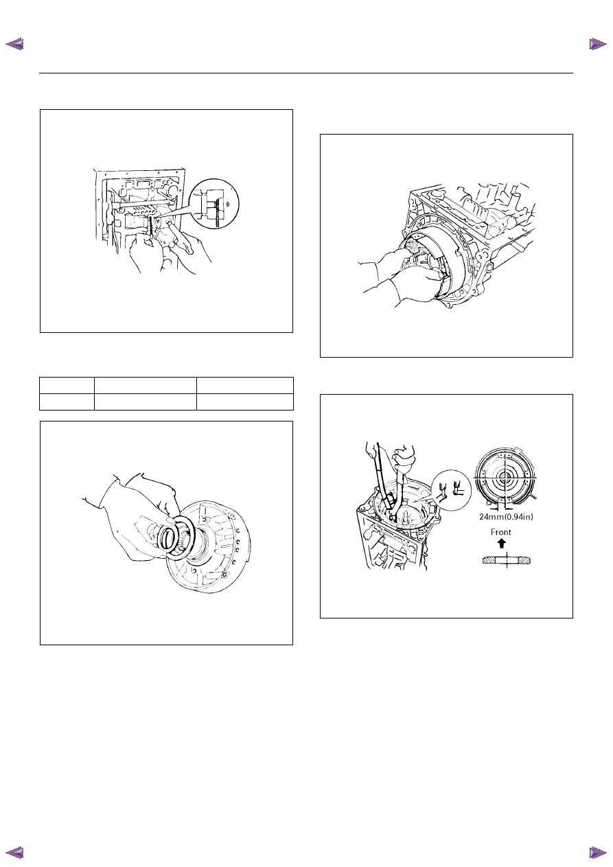
Using wire gauge, measure the stroke by applying
the compressed air (390 – 780 kPa or 57 – 114 psi)
as shown in the figure.
Piston stroke: 1.5 – 3.0mm (0.059 – 0.118in)
Inside
Outside
Bearing
and race
33.7 mm (1.33 in)
47.8 mm (1.88 in)
Legend
(1) Second coast brake piston
(2) Oil seal
(3) Piston rod
UNIT REPAIR (AW30–40LE)
7A4–31
If the values are nonstandard, check for an improper
installation.
248RY00004
23. Coat the race with petroleum jelly and install it onto
the overdrive support assembly.
Race diameter (Reference)
252RY00007
24. Aim the bolt and oil holes of the overdrive support
toward the valve hole side, and align them with the
bolt hole of the transmission case and insert the
overdrive support.
252RY00005
25. Using snap ring pliers, install the snap ring as
shown in the figure.
252RY00008
Inside
Outside
Race
36.7 mm (1.44 in)
50.8 mm (2.00 in)
7A4–32
UNIT REPAIR (AW30–40LE)
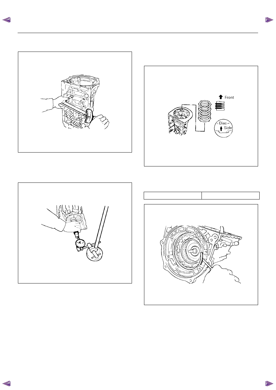
• Install and tighten the two bolts.
Torque: 25 N·m (2.5 kgf·m / 18lb·ft)
252RY00004
26. Check end of output shaft.
Using a dial indicator, measure the end play of the
output shaft by hand.
End play: 0.27 – 0.86 mm (0.0106 – 0.0339 in)
247RY00020
27. Install the (flat ring) 4.0 mm (0.157 in) thick flange
with the rounded edge side of the flange facing the
disc.
Alternately install four discs and four plates. (Disc
first)
252RY00009
28. Install the (stepped ring) flange with the flat side of
the flange facing the disc.
Install the snap ring.
Snap ring (Reference)
246RY00001
Inside diameter
167.9 mm (6.61 in)
Нет комментариевНе стесняйтесь поделиться с нами вашим ценным мнением.
Текст