Isuzu KB P190. Manual — part 337
EXHAUST SYSTEM 6F – 15
TURBOCHARGER
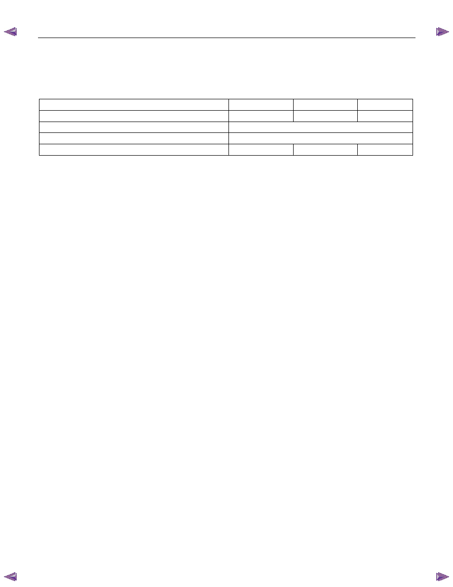
MAIN DATA AND SPECIFICATIONS
Engine 4JA1T(L)
4JA1TC
4JH1TC
Model
IHI RHF4H
IHI RHF4H
IHI RHF5
Turbine type
Mixed type
Compressor type
Backword & rake type
Maximum permissible speed rpm
190,000
190,000
180,000
IHI : Ishikawajima Harima Heavy Industries., Ltd.
6F – 16 EXHAUST SYSTEM
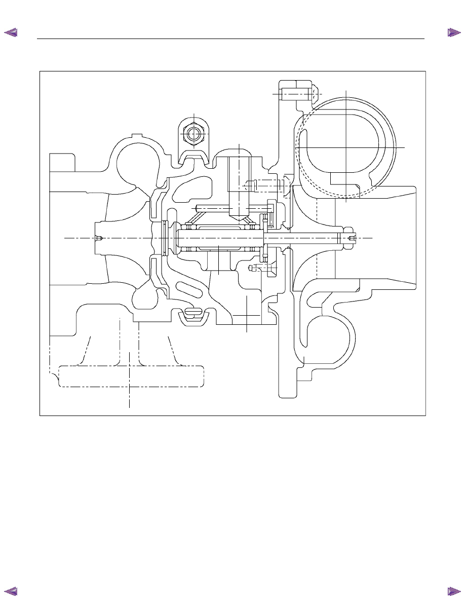
GENERAL DESCRIPTION
036LV002
The turbocharger internal mechanism consists of the turbine wheel, the compressor wheel, and the radial bearings.
These parts are supported by the bearing housing.
The turbocharger external mechanism consists of the compressor housing air intake port and the turbine housing
air exhaust port.
The turbocharger increases air intake efficiency. This results in increased engine power, reduced fuel consumption,
and minimal engine noise.
The turbocharger operates at very high speeds and temperatures. Part materials have been carefully selected and
machined to extremely high precision.
Turbocharger servicing requires great care and expertise.
If reduced performance is noted, check the engine for damage or wear. If there is no apparent engine damage or
wear, trouble with the turbocharger is indicated.
EXHAUST SYSTEM 6F – 17
INSPECTION AND REPAIR
Make the necessary adjustments, repairs, and part replacements if excessive wear or damage is discovered during
inspection.
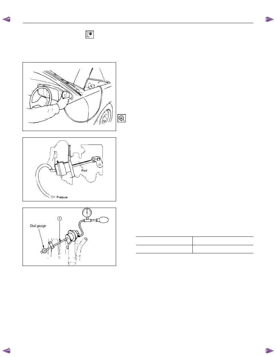
Turbocharger pressure check
1. Remove the hose between the waste gate and the
compressor outlet pipe.
2. Connect the pressure gauge. To compressor outlet
pipe.
3. Start the engine and gradually increase the engine
speed (the vehicle must be stationary with no load
applied to the engine).
4. Check to see that turbocharger pressure rises to
approximately 141.3 Kpa (1060 mmHg).
Pressure Gauge : 5-8840-0075-0
150RY00030
Waste gate operation check
1. Remove the hose between the waste gate and the
compressor outlet pipe.
2. Connect the pressure gauge. To waste gate actuator.
3. Check to see that the rod begins to move when a
pressure of approximately 118 Kpa (885 mmHg) is
applied to the waste gate.
Note:
Do not apply a pressure greater than 150Kpa (1125
mmHg) to the waste gate during this check.
150RY00031
Unit Inspection (Remove Turbo. from engine)
Check to see the pressure required to move the control
rod 2 mm is within the limits shown below.
Kpa/mmHg
4JH1TC 134.8/1011
4JA1TC 147.7/1108
150RY00032
Contact the “ISUZU MOTORS LIMITED” Dealer service
department or “IHI SERVICE FACILITY” for major repairs
and maintenance.
Important wheel shaft end play and bearing clearance
standards and limits are included below for your reference.
6F – 18 EXHAUST SYSTEM
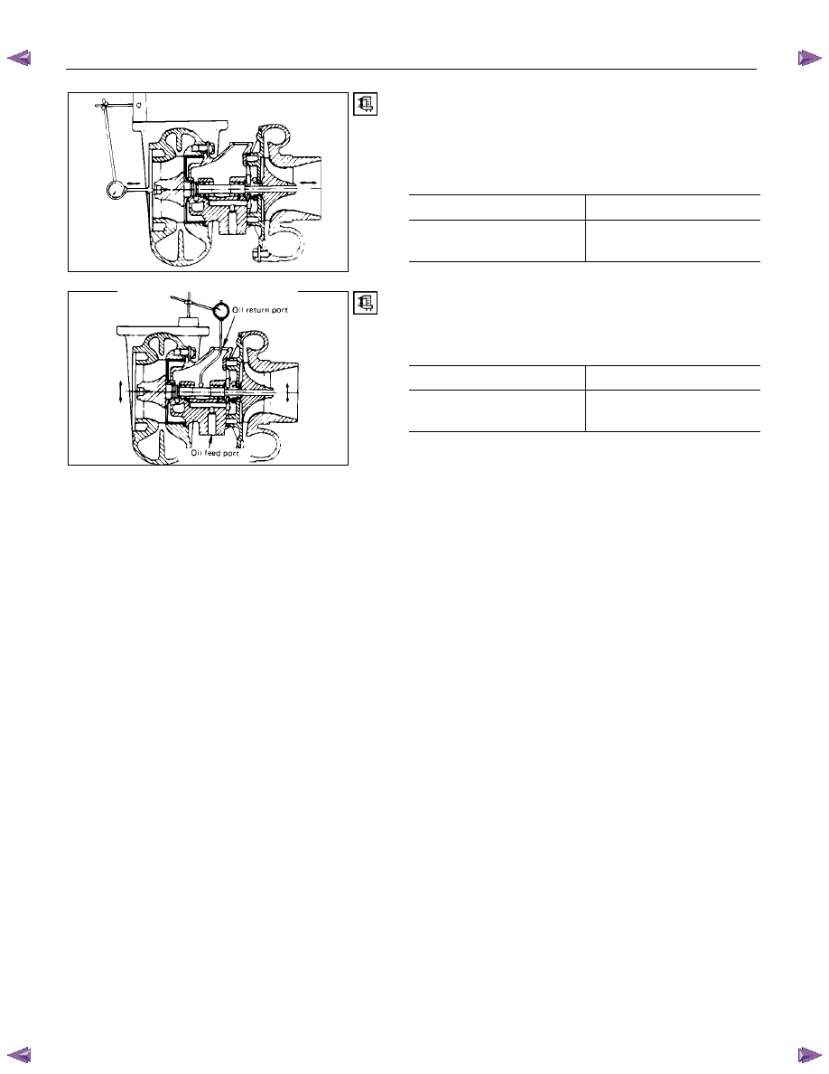
Wheel Shaft End Play
Use a dial indicator to measure the wheel shaft end play.
Apply a force of 1.2 kg (2.6 lb/11.8N) alternately to the
compressor wheel end and the turbine wheel end.
Wheel Shaft End Play
mm (in)
Standard Limit
0.03 - 0.06
(0.001 - 0.002)
0.09 (0.004)
150RY00034
Wheel Shaft and Bearing Clearance
Use a dial indicator to measure the wheel shaft and
bearing clearance.
Wheel Shaft and Bearing Clearance
mm (in)
Standard Limit
0.056 - 0.127
(0.0022 - 0.0050)
0.127 (0.0050)
150RY00036
Нет комментариевНе стесняйтесь поделиться с нами вашим ценным мнением.
Текст